

A Self-Filling Audio Player (Radio on Demand without Internet)
 Christof Eb.
Posts: 1,597
Christof Eb.
Posts: 1,597
Self-Filling_Audio-Player
This Project has morphed a little bit. It was initially meant as an "MP3 Player for a Person with reduced Eyesight". https://forums.parallax.com/discussion/175150/ideas-for-a-mp3-player-for-a-person-with-reduced-eyesight#latest The discussion over there opened my view that with large SD cards today MP3 is not really inevitable anymore. I then searched, how to obtain audio material. In this process it became obvious, that in my region there is a radio station SWR2 which broadcasts programs, which are probably of interest for the user person. So it would be nice to record certain broadcasts. Actually you can have podcasts of these, if you have internet access. Focal area of usage of this project is for speech, which must be clearly understandable, so hifi quality is not necessary here.
What does it do?
This is an Audioplayer, which fills itself (Audio files on SD-card) with radio broadcasts, which are sent regularly due to a fixed weekly timetable. There are 4 categories of broadcasts defined:
News,
"Wissen", which is 30 Minutes of in depth information about a topic;
Music,
Story
For each category there are 3 soundfiles with maximum of 2 hours length each available, which are overwritten in a rolling scheme. So you have available the last 3 broadcasts of each category.
For each category, there is a push button, which starts playing the last broadcast. If you press this button again, the next older one of this category is played.
There are also push buttons to stop audio and to start playing a fixed radio station directly.
There is an analog volume knob also.
A display is available, but it should be possible to use the machine without reading it.
So this is something like "Radio-on-Demand" without internet.
Implementation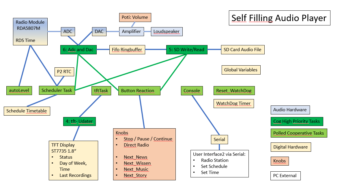
Challenges:
Audio has to be sampled with an accurate clock rate.
On the other hand, while SD cards are most often very fast, they can have "write latency". The internal controller then needs very much longer to write the data as on average. See here for some examples: https://jblopen.com/sd-card-benchmarks/
Why P2?
To achieve the completely accurate adc and dac clock rate, this project uses a dedicated core for adc and dac. When recording, this core/cog writes into a circular fifo buffer. A second cog tries to keep this buffer empty and writes to SD-card. For playback the chain is reversed. Now the SD-card cog tries to keep the buffer filled and the dac cog reads from it. While such things can be done with interrupts on other controllers, it is very much more easy to use dedicated cores. Additional cores are used for display, scheduler and button user interface.
During the project I learned, that the quality of the ADC of P2 is adequate for this project. On the contrary to 16bit CD quality, FM radio broadcasts dynamic range are compressed because of reduced Signal/Noise ratio. The datasheet of the FM receiver chip states S/N=57dB.
20*Log10(2^10)=60,2dB
Frequency bandwidth of the radio chip is 100Hz…14kHz.
An enabler to use P2 for the project was the Kiss board. https://forums.parallax.com/discussion/172225/kiss-eval-board-general-discussion/p1 Many thanks here!
Why Forth (TAQOZ)?
An interactive language is very convenient during software development, as you can always try out small samples of code, whithout of the need for debugging code. Or perhaps sometimes with small debugging code. Forth is the simplest in a row of interactive languages Forth-Lua-MicroPython. Because it is simple, it is fast and it is compact. With Forth, there is no problem to have a lot of library routines, a compiler, an interpreter, an assembler, a video buffer and the application on board of P2's 512kB without external RAM. Taqoz Forth makes it even possible to have allmost full access to the interactive console in parallel to the running application.
Many thanks for Taqoz and many thanks for the Glossary, which makes it usable!!!
For convenience and better readability I like to use value type variables and local value type variables.
Display
A 1.8' ST7735 TFT display is used. In Taqoz there is a bitmap VGA driver, which is modified to use 4 colors (2 bits). It is possible to switch the print channel from serial to the vga and back. There is a character set implemented. So here we use these nice features of Taqoz. The new ST7735 driver implemented here consists only of:
- A private SPI bus with separate pins, with it's assembler routines. Their bit bang code is largely copied from routines in Taqoz.
- Some Init routine.
- A routine to enlarge the size of graphics/text for better readability. Each original pixel in the left lower corner of the vga screen is copied into 4 pixels. This is done in place in the video buffer. After the process, the lower left quarter is enlarged to fill the whole screen.
- A routine, to convert the 2-bit VGA color code to 16-bit color code of the display and to send it to the display for each pixel.
Radio and Real-Time-Clock:
As a FM-radio chip RDA5807M is used. https://datasheet.lcsc.com/szlcsc/RDA5807M_C82537.pdf
These can be bought on very tiny breakout boards.
This chip has also RDS, which can provide day of week and time including summertime. It was one of the most time consuming parts of this project to get this working. A helpful site is:
g.laroche.free.fr/english/rds/groupes/0/groupe0A.htm#C1C0
Also very helpful (German): https://mikrocontroller.net/topic/313562
Received RDS data is often incorrect. To get the RDS time, the radio is switched to the strongest station and the RDS feature is switched on. It is a common method to wait for two consecutive equal results. This method can take it's time and I modified it here: Data is fed into a 3 stage fifo buffer and taken for valid, if the new result is equal to any of the previous results in the buffer.
Update: With a shorter antenna and lower signal strength, I had a lot of bad data. Now the procedure is more critical. It stores the two most frequent results and takes the top result, if it reaches a certain probability. The station sends 3 datasets just after a new minute. 5 of these 4 have to have the same time.
With this method time reception takes 1…3 minutes at my place. Every night at 3.30AM the P2 clock is set from the RDS. Taqoz provides routines to use the main counter of P2 for a real time clock.
For better audio quality, the RDS feature of the chip is switched off.
Update 2: As the reception of RDS time was not sufficiently reliable at the place of the user person, I now use a DS3231 RTC with battery backup. Every night at 3:30 a reboot will occur with for 10 minutes an attempt to update the RTC if plausible. For plausibility the date has to be completely accurate and the minutes within 2 and the hours within 2 (summer/winter).
Amplifier
A PAM8403 module is used as audio amplifier.
ADC and DAC
For ADC smart pin adc Sync2 mode, with gain 10, 8192clocks for 14bits resolution (S/N ratio is less!) with 24.4kHz sample frequency is used. So audio frequency bandwidth is <12.2kHz.
For DAC smart pin 16bit Dither mode is used. The adc gives the pace. A dedicated cog #6 is used for solid sample rate. Originally I planned to have a direct analog connection between the radio chip and the amplifier for maximum sound quality. Some sort of relay switch would be needed. At the moment there is no such line and even direct radio takes the route over the adc and dac.
Circular Audio data buffer and SD access
A 64kB buffer is used by a dedicated cog which uses Taqoz routines to read or write to SD. Taqoz makes it extremely simple to write to SD-card. Just open a file. To write a long into a RAM location, Forth uses the syntax:
DATA ADDRESS ! For example: 10 20 !
To write to SD, we can instead use:
DATA ADDRESS SD! For example 10 20 SD!
The address is relative to the beginning of the file. A 4kB Buffer is used to read or write chunks of data from/to SD. Taqoz takes care to always have the right buffer in RAM.
Dedicated cog #5 is used to handle SD- access.
Taqoz seems to have some limitations for the SD. I had some difficulties to use some 32GB cards. And I was not able to have more than 3*4 audio files on a 16GB card, which should have plenty of additional space.
There is a Forth word (Program) createAllAudioFiles to be used with the console to prepare the empty sound files, which use their own format.
Information to the Screen, Buttons, autoLevel, watchdog and Scheduler
Using the feature of polled multitasking these tasks are done in background by cog0, which also serves the interactive serial console. These tasks are state machine words, which are called each after another, when the console is waiting for key input. This method is suitable for less timecritical tasks and has the advantage of being cooperative. So only one of these tasks is active at one time and can use a ressource. Cycle time of these polls is normally 6…66 ms. Only RDS time decoding blocks any other activities.
AutoLevel is a slow compressor, which reduces audio output of the radio chip, if there is overflow. After some time, when only low level was detected, the volume is increased.
There is a regular timer interrupt implemented in Cog0, which is counted. If the counter is not reset, the timer-interrupt routine will cause a reboot. The regular reset is done by a polled task. So this can check, if the Taqoz polled tasks are still working. The scheduler also does reboot every night at 3:30am, which causes the system to get the accurate RDS time.
Writing to the display is split into 2 tasks. The fist step writes text to the vga buffer and is done by a polled task. Then cog #4 takes over, enlarges the picture then converts and sends it to the display. As enlarging and sending data takes some time, splitting helps to keep low the cycling time of the polled tasks. Handshake is done with a global variable.
For simplicity of handling for the user, settings like the broadcast frequencies/stations or the timetable must be edited in the source code and cannot be altered without PC.
Console
As all tasks of the device are done either as separate cog tasks or as background polled tasks, the Forth serial console ist still fully available. This can be used to inspect global variables and so forth. As Taqoz only allows one open file, here is necessary some caution.
One poem a day
There is now the feature added, that if you long-press the blue (green) button, then you will hear one preselected-per-day poem (ballade), stored as WAV files on the SD card.
=======================================================================
Source is included as is. It could be more tidy, I think.... If there are questions, just ask.
Comments, suggestions? - Does somebody know some DAB+ module for an attractive price?
I always receive much help and interesting inspiration from so many people here, many thanks!
Have fun!
Christof

Comments
An excellent, multi aspect write up.
Thank you.
The SD card quality issues are real. Do note that some cards will intermittently have extremely long access times that throw off any sufficiently short buffer. And the ones that have reliable access times are oddly enough the ones that generate more electrical noise. See: https://junkerhq.net/MDFourier/notes/note7-sdcardnoise-3.html . SanDisk is of the noisy type. I've been able to get away with a 2x256 byte buffer for audio playback (32kHz 16 bit stereo).
A trick I've found to get SD access times under control: NEVER RELEASE THE SELECT LINE EVER. On the SanDisk card I usually use, one random sector read usually takes on the order of ~400µs. If the select line was idle for more than ~10ms though, it will take significantly longer. The SD protocol doesn't rely on the chip select pin for framing, so you can just leave it permanently enabled (or until you access another device).
Hi, @Wuerfel_21, thank you for the input.
Question about that noise: Does this come into the system by variing DC current consumption of the SD card, which then leads to supply voltage sag of the controller and it's DAC? Then perhaps it would be good to have a separate power supply for the SD card? At the moment I think, the bigger noise problem in my setup comes from the display or from copying it's contents from P2 to it. At least you can hear some "cirp" every second. But at the moment there is no shielding at all in my setup, so perhaps there is some improvement possible here.
Some other idea: There is deemphasis switched on in the radio receiver chip. Perhaps it it would be an improvement, to shift that filter to the position after the DAC. As far as I understand this is a simple RC low pass filter with f=3200Hz in Europe.
Unfortunately the radio chip has an output of only 320mV (datasheet). Seems to be V.eff? 3.1*gain is needed in the adc but about one bit per sign side is lost, because 5V/3.1/2=0.8V Amplitude are never reached. So here is a path for noise to creep in.
As far as I know, the latencies for write can be very much more long than for read, because they occur, if the controller has to erase flash or did detect a bad/weared chunk of flash.
The KISS board doesn't have isolated VIO regulators like the Parallax board... But even on my P2EVAL I can hear the SD card noise, so I'm not sure. Maybe it also travels through the ground pin.
Yea, you could try that. An analog RC filter is equivalent to a digital IIR filter.
Isn't the DAC range from 0 to 3.3? I think you could just use the 10x ADC mode in that case.
Yes, write latency can be much worse due to flash management.
Good project!
The RDA5807M looks like another SDR receiver chip. Possibly a clone of or inspired by SiLabs. It seems ironic to me that the radio signal is digitized in quadrature, processed digitally, and then output as analog. Only to be digitized again by the P2.
If the radio used older super-heterodyne technology, then maybe the 10.7MHz intermediate frequency signal could be fed into the P2. That way analog noise in the circuit could be rejected by the FM demodulation process.
If you are only receiving a few stations, it may be possible to adjust the P2 clock frequency for better sound quality. The harmonics from things like the SD card clock could cause interference.
Hi,
RDA5807M was inspired by Philips TEA5767. Yes, it is kind of silly to do these analog digital conversions twice. It would be nice, if the chip enclosure had I2S Pins. As far as I understand, this would be RDA5808SP. In Germany, analog FM Radio broadcasting is due to be switched off. It was even planned to be switched off in February 2023. So I think, the way to go is DAB+, for example with Si4684. https://skyworksinc.com/-/media/Skyworks/SL/documents/public/data-shorts/Si4684-short.pdf Unfortunately I have not yet found a breakout board for a reasonable price.
Of course it would be interesting to know, if P2 itself could possibly decode DAB+? Such project would clearly be out of my range of skills. :-)
Christof
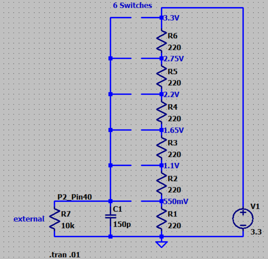
Hi,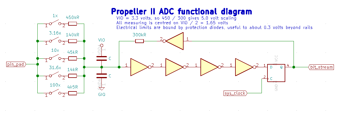 This picture is very informative, because it not only shows the voltages but also the variing input impedance. It's by @evanh . https://forums.parallax.com/discussion/comment/1484327/#Comment_1484327
DAC range is 0...3V3. ADC with Gain 10 range is +/- 250mV, centered around 1.65V.
Update in first post:
Bugfixes.
A software compressor is used now to get the most from the adc, which has now gain 10.
Also I had to make the RDS time decoder more critical, because it let wrong results pass too easily. The radio chip detects the wrong RDS data group, if the signal strength is too small. Then repeated wrong data can get into the procedure.
Updated.
Bugfixes. Instead of just brute-force-stop the fifo-cog, this is now done more delicately. There had been hang-ups in corelation with the SD card, therefore we now have a watchdog and additionally regular reboots.
Also we now can pause and continue playback.
Still there is a problem at the location with weaker FM radio reception. I have to use an indoor antenna, which is just a wire. For sound quality the signal strength is sufficient, but the RDS data is bad quite often and the newer rejection routine still does not filter out all bad data.
My radio knowledge is "somewhat limited". At the moment I have tried to add a preselector coil. 4 windings, air D=10mm, length about 15mm. Idea is from here: https://to-st.de/content/projects/si4735lin/preselector.de.html Unfortunately the RDA5807M's input impedance seems to be too low, so you can't use the coil as transformer. I have now ordered a broadband amplifier module and hope that this will improve things.
If someone wants to point me to a powerful FM radio indoor antenna 107.5MHz solution, I would be grateful!
Christof
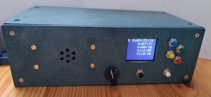
Updated ZIP in first post.
Also included a photograph of the player.
Still have had problems with the RDS time/date. On one hand there was a plain bug in the routine to calculate the "modified julian day", which showed now up after months. On the other hand there was still totally wrong time / date some times with "bad" radio reception.
To check for plausibility, I now added, that the date must be in a certain range from now until the next 20 years. Also the local time offset must be +1 or +2 for German winter or summer time.
So there are now these two new checks, the check, that the "valid" data has to be received 3 times more often then any other data and the built-in bit checks. You would think, that this is enough now???!!!
Time and date is now updated only on Fridays 3am. Although at any time a long press (>3sec) of the black key will now restart the machine including time set.
At the moment I think a simple passive 2 wire dipole antenna is best. If all of the measures to improve reliability of the time setting won't work, I will have to resort to manual time setting. (The problem is, that the user person cannot do this.)
Update:
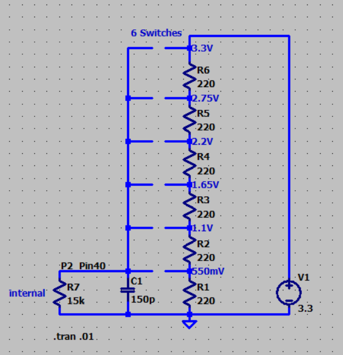

The device has been given to the person with reduced eyesight. It turns out, that the person cannot read the display. Unfortunately without visual feedback it is a major problem, that the keys do not work very reliably. These keys have varying contact resistances and need a firm press. I will now add a capacitor 150p and the software for the reading of the keys is improved.
I would not recommend to use this type of reading the keys via ADC any more. Perhaps for some keys with gold contacts.
The last optimisation of the RDS time decoding, which rejects non-plausible data, together with the dipole antenna did the trick regarding reliability of the day and time.")
I now will switch over to a compare with 8bit DAC - ADC to scan the keys. Reason is, that for DC measurements obscure regular recalibration is needed: https://forums.parallax.com/discussion/175191/adc-topology-using-two-pins-that-needs-no-calibration#latest
Now an external pulldown of 10k is used. Edit: 33k for to work better with varying switch resistance. First impression is, that it works better than the sigma delta ADC. Will have to solder the external pulldown 10k into the device.
Implementation with simple ramp.
: comp8 ( threshold -- true/false ) \ 8 bit comparator
   keysPin pin
   8<<
   %0000_0000_000_11000_00000000_00_00000_0 \ Level comparator ( with 1k5 output if enabled )
   or wrpin
   F \ set pin to float ==> disables output
   1 us \ allow to settle
   R \ read pin state as input
;

: compAdc ( -- value )
   0
   begin
      1+
      dup comp8 0=
   over 254 > or until
;

0 value lastRaw#

: rawAdc \ print adc results
   key drop
   begin
      10 ms
      \ keysPin pin
      \ 10_000 adcDrive
      \ 100 us
      compAdc
      dup lastRaw# - if
         dup .
         to lastRaw#
      else
         drop
      then
   key until
;
rawAdc brings either 1 or 2 as result with the external pulldown 10k close to the pcb.
First I tried to avoid the need to solder the 10k using this neighbour pin compare method but gave up after 2 hours. The documentation of P2 is a real problem, if you don't want to spend days with experiments....
Hello Christoph
Have you tried my SAR-ADC here:
https://forums.parallax.com/discussion/173944/
This needs no second pin, just the one ADC input. It has very high input impedance, so switch resistor does not matter much.
To use an internal pulldown with this SAR-ADC, you can just change the
wrpin(pin, 0)to something like:wrpin(pin, P_LOW_15K + P_OE)With that, the pulldown will only be active when no ADC conversion is in progress.
Andy
Thank you , @Ariba . Certainly sar would be more elegant than my slope!
I can easily use a stepped ramp to just test at the few threshold levels between the switches. For testing and to know what is going on I preferred to have the full ramp for now.
Your code is thriving to be fast. Funnily in my application I do a lot to make it rather slow to filter out contact problems like bounce.
Christof
Edit: To use an external pulldown resistor is probably the better way. So it is more easy to find a good compromise to be fast, to have some load on noise coming from the wiring and radio and to have low load on the switch contacts.
Update: As the reception of RDS time was still not sufficiently reliable at the place of the user person, I now use a DS3231 RTC module with battery backup. Every night at 3:30 a reboot will occur with an attempt limited to 10 minutes to update the RTC if plausible. For plausibility the date has to be completely accurate and the minutes within 2 and the hours within 2 (for summer/winter) between RDS and RTC. The code for DS3231 could be ported relatively easily from the code for RV-3028 in EXTEND.FTH . It is also possible to use alarm registers in the RTC as a permanent miniature scratchpad.
Also I now switched to the faster local variables, which are held in COG ram to be consistent with my other newer projects.
Code in first post is updated.
Update: Disadvantage: The person with reduced eyesight will not be able to do it.
Something rather strange happened: When I had posted #16, I had tested the DS3231 RTC module and the code to use it with my breadboard version of the hardware and both RTC and radio worked. When I then soldered the RTC module into the other permanent hardware with enclosure, the radio chip could not be accessed any more. RTC and radio chip shared the same pins at P52 and P54 for I2C. When I desoldered the RTC the same software with the radio chip worked. When the RTC was connected, it could be accessed but not the radio chip.
I then changed both the radio and the RTC modules using the ones, which I had used in the bread board, but had the same symptoms.
After spending several hours with that miracle, I now use 2 different I2C buses. Radio uses P52/P54 and RTC uses P41/P42.
Also now there is a crude way to just set the date and time manually using the knobs and the display.
Code in first post is updated.
One more update:
I had been wondering, how to make the player more attractive?
The user person loves poems.
So there is a new feature: The player can now play WAV files. As we deal with NON-Hifi quality for spoken here, for simplicity only one channel and only every second sample is put to the DAC with sample frequency 22050Hz. (What a waste of SD space....) So there are now 77 poem-ballades plus 134 poems on the SD card. This is about 8 hours of audio. To have a way to handle this for a person who cannot see a text display, there is simply one poem plus one ballade preselected each day. Like these old calendars with a joke a day.... A long press on the blue button starts the poem and a long press on the green starts the ballade.
To make the handling of the source code more easy, I have split the code into 3 files, which are to be named auto.f , auto1.f and auto2.f .
Code in first post is updated.
I think, this project is approaching some final stage....