

ADC topology using two pins that needs no calibration
 cgracey
Posts: 14,323
cgracey
Posts: 14,323
One of our customers needed a low-noise 8-bit ADC that doesn't require any calibration.
I made a simple tracking ADC that uses P0 as the signal input, which also feeds that pin's comparator(+) input. The P1 pin is in 124-ohm 3.3V fast DAC mode and it feeds P0's comparator(-) input. You chase the input signal with the DAC via the comparator. Because we use 16-bit dithered DAC mode, we can chase at a step rate that is a fraction of an 8-bit LSB, keeping noise low.
Here is the code:
CON

  _clkfreq = 320_000_000
  pin_pair = 0

PUB go()

  coginit(newcog,@track,0)

DAT             org

'P0 is the signal input and comparator(+)

track           wrpin   ##P_COMPARE_AB,#pin_pair+0

'P1 is the DAC output that feeds the comparator(-) on P0

                wrpin   ##P_DAC_124R_3V|P_OE|P_DAC_DITHER_RND,#pin_pair+1
                wxpin   #1,#pin_pair+1
                drvl    #pin_pair+1

'Loop to adjust the DAC level on P1 to balance against the input on P0

                rep     @.r,#0                  'repeat forever, fast

                testp   #pin_pair+0     wc      'test comparator
                sumnc   level,#$55              'ramp 16-bit DAC level up or down, $55 = ~1/3 LSB
                fges    level,#0                'clamp negative at $0000
                fles    level,hFF00             'clamp positive at $FF00
                wypin   level,#pin_pair+1       'set DAC to $0000..$FF00, level.[15..8] is the "ADC" output
.r


level           long    0
hFF00           long    $FF00
spin2
802B
Comments
Impressive. Utilises the precision of the Fast-DAC. High impedance too, which sometimes matters.
I was about to say even the sigma-delta ADC doesn't really drift enough to upset 8 bits I don't think. But the tracking method could achieved far better than 8 bits. The DAC is estimated as good for 12-bit effective I believe. Although, that's also about what can be expected from the ADC with a repeating calibration.
EDIT: Oh, not so much the drift but the uncalibrated difference from one sigma-delta ADC to the next is huge! And the simple calibration method doesn't do better than about 5 bits when comparing different pins.
I also did an 8-bit single pin equivalent using the CompDAC pin mode - https://forums.parallax.com/discussion/174441/measuring-floating-pin-voltage-adc-from-just-the-built-in-comparator/p1
It isn't quick though, given the time it takes for the slow-DAC to settle. Looking at the code, about 16 microseconds.
EDIT: I suppose mine could be rewritten as a tracking ADC too.
The internal comparison DAC uses R-2R topology, so there are disruptive spikes when it switches, with the worst being at the $7F-$80 transition. It's meant for steady-state applications.
Yep, it's slow to settle. Many instrumentation uses are steady state.
I suppose it might be really rude to suggest that the ADC use Gray Code for resistor switching. That way only one bit ever flips at any given transition.
S.
Comparator's DAC, not the ADC. But yep, Gray-coding the wiring would be cool. Add some Gray instructions, for incrementing and binary conversion, and we'd be sweet for making a tracking ADC from the comparator.
I think
fgescan be avoided, makingreploop shorter:'Loop to adjust the DAC level on P1 to balance against the input on P0 test level wz rep @.r,#0 'repeat forever, fast testp #pin_pair+0 wc 'test comparator if_c_or_nz sumnc level,#$55 wz 'ramp 16-bit DAC level up or down, $55 = ~1/3 LSB fles level,hFF00 'clamp positive at $FF00 wypin level,#pin_pair+1 'set DAC to $0000..$FF00, level.[15..8] is the "ADC" output .rIs there any advantage now in replacing
$55with$33?That's crazy, TonyB_!
I didn't think it would work, but I tried it, anyway, and it DOES work. Then, I had to look at it very closely. Slick how it uses Z to avoid rolling under. I don't know how you figured this out.
Yes, you could make the step size smaller, since it's faster. My hope was that a fractional-LSB step size would keep it dithering within a single 8-bit value, until you reached the threshold of the next value. Of course, the comparator has some hysteresis, maybe 10mV or so, which is just under 3.3V / 256 or 12.9mV.
How would we grayscale an R-2R DAC? I think we'd need some other topology that would lend itself to grayscale coding.
Oops, you're right. R-2R is binary to its core! :O
A Gray-coded network would look quite differently built then.
EDIT: Whoa, I found something amazing. Check out this whole paper - https://gair.media.gunma-u.ac.jp/dspace/bitstream/10087/11580/1/15804102Gopal Adhikari(アディカリ ゴパール).pdf
And what appears to be a humorous accompanying lecture - https://kobaweb.ei.st.gunma-u.ac.jp/news/pdf/2016/2016-6-25LSI-gopal.pdf
A quick look over their lab setup for glitch testing suggests, without any clocking/latching, they may have badly done the binary-to-gray converter so that it was introducing unnecessary timing glitches into the digital sequencing.
I think they could have got even better results than they did.
Here is the part of the .pdf where they reveal the topology of the Graycode DAC.
It works by swapping nodes within a simple resistor network. It actually IS an R-2R network, of sorts:
This would involve making very constant-impedance transmission gates in silicon.
Yeah, not complicated at all. I'd previously seen the same XOR'ing effect with the digital convertor too, so that figures really.
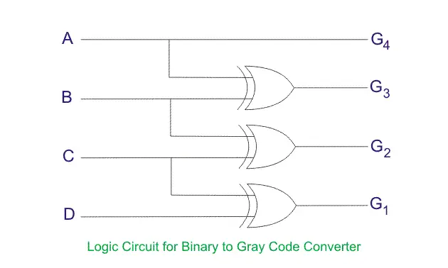
EDIT: Hmm, the diagram ain't the clearest. A-B-C-D would be better written as B3-B2-B1-B0. And G4-G3-G2-G1 as G3-G2-G1-G0.
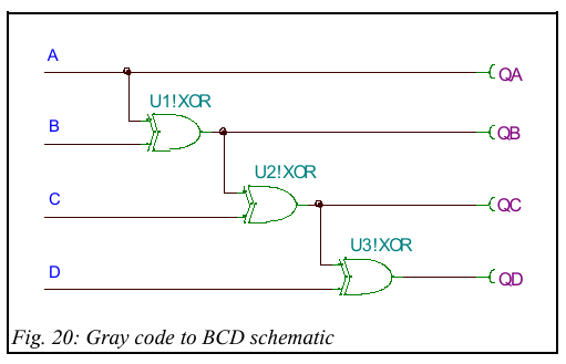
Interestingly, to convert back to binary has hints of a binary adder with its cascade of XORs.
I'd prefer using external ADC's to do the heavy lifting
In my mind, P2 has pretty good ADC and a lot of pins. So, I'd use them if it's just a few channels of ADC needed. Probably want to use an LDO for VIO of pins used for analog.
For simple DC level measurements, the internal ADCs not only drift with time and temperature, they are dramatically different between themselves. Calibrating between GIO and VIO does improve things, but it is far from a silver bullet.
Whereas the precision and linearity of the DACs makes them an excellent level to compare against. As long as VIO is stable, Chip's solution above won't drift with time or temperature or use of different pins.
I haven't actually tested my linked code for linearity and stability of the comparator's R2R DAC over time and temperature. I would hope it is pretty good too. Its main expected limitation is having to wait for the R2R to settle when adjusting it. That and it's also 8-bit only.
Are there some numbers about the amount of drift available? I have problems with my ADC reading of 6 keys. Because there I need only 4bit repeated precision, I thought, that recalibration is not necessary.
Thanks!
Christof
That's one of six, not any-of-six reading, right ?
If your design can tolerate a driven ADC pin (resistor keypads should be able to be ok) you might be able to get better calibrate by drive of the pin HI and LO. IIRC P2 can do that ?
and maybe a square wave drive can calibrate a 50% point too, using the ADC averaging nature.
Wouldn’t doing the internal calibration befor every measurement solve any drift concerns?
Not sure. I've stated 12 bits in the past but aren't particularly confident on that any longer. ManAtWork did a more complicated calibration that might have yielded that good.
There was suggestions of pairing two ADC as a gang and average them. Chip, I think, had improved results this way many moons ago.
It is "rather strange", that @cgracey suggests to use 8bit ADC as an improvement here while https://docs.google.com/document/d/1gn6oaT5Ib7CytvlZHacmrSbVBJsD9t_-kmvjd7nUR6o/edit
still advertises "* ENOB = Effective Number of Bits, or the sample resolution" of up to 14bit, without even mentioning, that you have to recalibrate with temperature. (Noise limits the real ENOB to about 12.4bits best case but this number does not incorporate drift).
It would be very nice to have proper documentation for P2 on which you can just rely....
That applies to audio and the likes, rather than instrumentation. The AC abilities of the ADCs is pretty good. DC capabilities of the ADCs were intended to be better than they are, but that wasn't to be. Knowledge is lacking on how to make them better.
Agreed, more detailed datasheet-like specs is required. Prop2 has way more hardware features than the Prop1 so it's a lot more work to cover everything. And, of course, Chip has been focused on fleshing out Pnut over the past couple of years.