

FM Radio transmission using colorspace converter
 Wuerfel_21
Posts: 5,862
Wuerfel_21
Posts: 5,862
in Propeller 2
It turns out the chroma modulator is vaguely competent at generating an FM carrier wave.
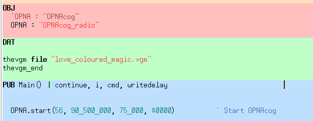
I've included a version of OPNACog that has been modified for FM radio use, but the basic gist of it is:
- the higher the clkfreq, the less distortion (in theory)
- compute
centerfreq := channel_in_hz frac clkfreq - compute
bandfreq := (deviation_in_hz frac clkfreq)+/$8000(assuming your internal samples are 16 bit) - enable some pin(s) in DAC channel mode
P_DAC_75R_2V|P_OE|P_CHANNEL|(cog<<8) setdacs ##$00_00_FF_01setcmod #%11_1_000_0setci ##$00_00_4D_80- in a timed loop (important, setcfrq applies immediately), do setcfrq with centerfreq + sample*bandfreq
- the receiver will apply a simple one-pole low-pass filter. In my case, the signal was already lowpassed internaly, so I just disabled that to kinda counteract it. Making a proper pre-emphasis filter wouldn't be too difficult though.
Welcome to Kirisame FM 90.5 MHz, where we play love_coloured_magic.vgm, all day, every day.

Comments
Oh man, would I love to be able to generate AX.25 in the 2 meter ham band. Being able to create an APRS tracker without having to feed a radio would be cool! I suspect since this is for broadcast FM, the deviation is wide. Any idea if it could be reduced to 5kc?
Going to have to check this out over the holidays!
2 meter might be pretty bad wrt signal quality, since that's a lot closer to the nyquist frequency of a P2 running at ~320 MHz. The deviation is selectable, though with the simple deviation calculation I'm using (
centerfreq + sample*bandfreq) it quantizes to pretty big steps. This could be solved better if by changing it tocenterfreq + (sample*bandfreq)~>10or smth, which would allow more precision.Oh, and the transmit power from just a pin is obviously rather weak. Would need some kind of amplifier for long-range use.
EDIT: Perhaps
P_DAC_75R_2Vis not the optimal DAC mode... No idea how I'd measure which is better though.I wouldn't try transmitting anything over any kind of range -- birdies galore. Even the P1 with its asynchronous PLLs suffers greatly. I have to imagine the P2 would be worse.
-Phil
Yea, not without a band-limit. Maybe this has less overtones than the P1 PLL... That's just square waves, whereas the CSC at least makes an attempt to generate a sine wave (of course the modulator isn't bandlimited either way)
Overtones are not the issue. They can be filtered out. Birdies, caused by jitter, cannot be filtered.
-Phil
I wouldn't want to amplify it. Just use it as a balloon tracker. I have one that uses a micro to beacon FM modulated CW. 50mw at 100,000 ft was quite easy to hear with an HT. I will have to go look and see if it is using the clock circuit as a fundamental oscillator or a pin output. Had to DF two balloons with it, where the tracker had failed.
I have very little understanding, and no experience, of any of this but the main clock PLL I think is pretty stable in the Prop2. Compared to the Prop1 at least. Synthesised output I think will be low on the random jitter.
EDIT: I suppose I do have one tiny amount of experience just generally looking at clock stability using a scope - Just to compare when running the PLL below spec. And What I found was an apparent linear degradation as the VCO frequency lowers below the rated minimum 100 MHz. But with bad spikes in the 20-30 MHz region, particularly near 20 MHz. Which I presume is an interaction with the 20 MHz reference crystal on the Eval Board. I didn't look below 20 MHz.
The potential issue I see with the P2 is that its outputs are synchronized to the main clock. When an edge has to occur where it doesn't "want" to, you get jitter. On the P1, the PLL outputs are not synced, so edges can occur where they belong. But the shortcoming of the P1 PLLs is that the filter on the phase detector has a pretty short time constant. So NCO jitter doesn't get filtered out downstream as well as it might be.
-Phil
Yea, but there are no edges here, only analog samples on a sine wave, which are inherently band-limited.
If you're trying to output a 145 MHz analog sine wave signal sampled at 320 MHz, say, you will have edges. The just won't be logic-level edges. But nor will they look anything like a sine wave.
-Phil
That ain't random though. There will be a specific beat.
Elaborate, please?
-Phil
Like the NCO rollover. The target frequency is there but there is also the beat with the sysclock frequency. If the two coincide then it's clean, if not then they beat.
Got it. And that "beat" is what defines the spurious sideband peaks ("birdies") caused by jitter.
-Phil
The frequency control resolution on the chroma modulator and DDS/Goertzel hardware is much smaller than 1Hz. So operating at 5khz deviation would be fine.
If you operate the P2 at 320Mhz, a 146MHz signal will have an image at 174MHz. The formula is Fi = NFs +- Fo , For the example, 1320 - 146 = 174.
Another option is operate the P2 at 195MHz. The desired 146MHz signal would then be in Nyquist zone 2. The signals would be at 49MHz, 146MHz, 244MHz, and so on. It might be easier to build a bandpass filter for 146MHz that filters out these frequencies instead of 174MHz. It will loose some output power operating in Nyquist zone 2.
This is not a bad reference to explain Nyquist zones. https://www.ti.com/lit/an/slaa523a/slaa523a.pdf The modulator circuitry shown here is really similar to the chroma modulator. Also shows the different methods of upconverting the signal including a low pass filter/ interpolator, which the P2 doesn't have.
The P2 was not designed to be a radio transmitter. That said, here are my recommendations for getting an FCC passable spectrum or close to it:
Use the Goertzel hardware instead of chroma modulator. https://forums.parallax.com/discussion/174719/chroma-modulator-blues All those little jaggies are harmonics that will alias down, potentially into the passband.
Use a PLL PFD frequency of 80-125MHz. This means feeding the P2 from an 80-125MHz crystal oscillator and div=1.
https://forums.parallax.com/discussion/comment/1464344/#Comment_1464344
Signal purity should be excellent if the P2 is running off the crystal oscillator with no PLL active. But that could result in a reduced system clock frequency. It should be good enough feeding the highest PFD frequency possible and doing a 2x, 3x, or 4x multiplication.
Could the P2 handle more than 125MHz input? If so, that would be great!
I would've thought that was an overtone.
An overtone is part of the harmonic series above the fundamental. It has nothing to do with jitter.
-Phil
I wasn't calling it jitter.
But jitter, not an overtone, is what causes spurious sideband peaks. And the reason they are peaks, and not random mush, is due to the beats you alluded to.
-Phil
I consider jitter as a random effect.
I don't know. As I stated at the outset, I really don't have the knowledge so probably shouldn't have poked my nose in at all.
Bothered to record a video demonstration.
The reception would perhaps not be as affected by me touching the tx antenna if the receiver actually had any antenna connected (it's supposed to plug into a roof antenna or smth). It also works on my phone's FM receiver (suck it iSheep, my phone has IR, FM Radio, TWO HEADPHONE JACKS and an easily swappable battery)
BTW, has anybody tried to build an aircraft radio with the P1 or P2? This uses AM in the frequency range 118 to 137 MHz. The latest standard has a chanel spacing of only 8.33kHz so there are 2280 channels. Because of the narrow channels and because both transmitting and receiving is required I wouldn't use direct synthesis but instead use the Goertzel mode to generate and de-modulate the IF of ~10MHz and use an external mixer and IF filter.
Ignoring the slight low-resolution-ness of the IQ modulator, it will look like a perfect sine wave if you filter frequencies above sysclk/2. That's the nyquist-shannon sampling theorem. The bigger problem is that the modulator isn't bandlimited (i.e. NCO frequency only changes once instantaneously per sample, creating all sorts of overtones)
So does the analog output value correspond to the instantaneous value of the sine wave at the sample point, or to the mean value of the sine wave over the sample interval? Or does it matter?
-Phil
It's the value at the sample point (
sin(Ft))@Wuerfel_21 Nice work! Neat to show that works.
If you use the streamer in DDS mode, where you make a 512-byte lookup table for a sine wave in the LUT, then control the frequency (modulation) via SETXFRQ, it might be a little better quality.
Nice job, Ada.
Yeah, but that uses up the LUT memory and thus couldn't be hacked into the existing synth objects. Not sure how much the sine quality actually matters at frequencies that high
Yeah, maybe it doesn't matter.
Using the LUT for something else is a good reason not to do Goertzel. I think it won't affect sound quality. The stairstep wave I showed using the chroma modulator suggests that all the distortion is above the 10th harmonic or so. A Raspberry Pi has great sound quality, but the spectral purity was terrible until I demonstrated that the fractional N PLL could be modulated with music. It's in my github. An FM radio only looks at 200kHz around the tuned frequency. So out-of-band spurious emissions don't affect sound quality.
I think the chroma modulator will show a lot more spurs on the spectrum analyser than Goertzel mode.
If you use the chroma modulator to generate an audio frequency sine wave you might hear the distortion.