

Chroma modulator blues
 SaucySoliton
Posts: 585
SaucySoliton
Posts: 585
The documentation mentions that the chroma modulator uses a 5 stage CORDIC. Now even I am not such an expert of CORDICs that I know the performance characteristics just by reading the description. Here is a graphical representation of what that means: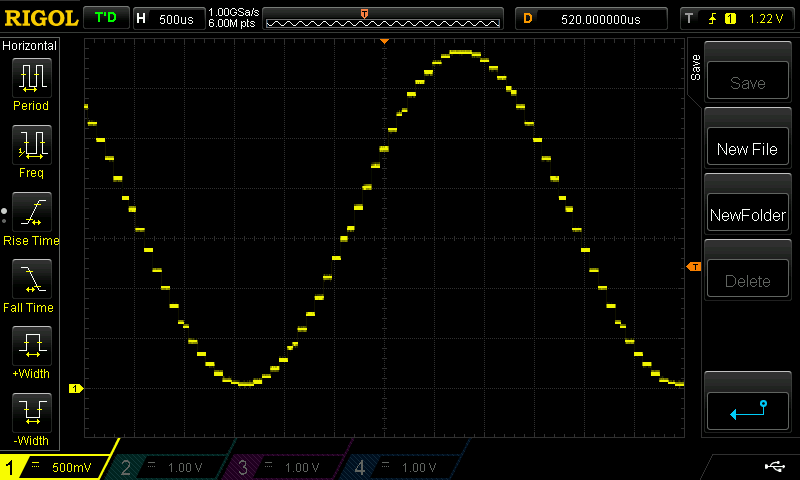
If you connect this to a speaker you can hear the distortion. It probably adds a small amount of picture distortion to composite video.
The chroma modulator is a quadrature modulator. Exactly what is needed for a software defined radio transmitter. I would not want to transmit this waveform over the air.
For comparison, the waveform from the Goertzel circuit:
I don't know if the 512 sample look up table is enough phase resolution for a high performance radio transmitter. Hopefully it is...
For both of these, the P2 sysclock was 240MHz, and the output frequency was about 228 Hz. So I will be using the streamer for any radio transmitter projects.
Comments
No, not really. The 5 stage cordic is already somewhat overkill. A lot of serious video equipment just emits a 4 step quadrature square wave "+I +Q -I -Q". The harmonics generated by this fall outside the bandwidth of an SDTV signal.
(The actual issues with the modulator are that the DAC can't drive the peak-to-peak voltage required for 100% yellow and that the IQ values are fed into the modulator with no filtering (and relatedly, lack of chroma trap for the luminance))
I doubt that you will ever get a clean-enough signal from the Prop (either P1 or P2) for RF transmission. Although harmonics can be filtered out, birdies caused by frequency jitter cannot be.
For an RF transmitter, you'd be better off using something like an SA612 oscillator/mixer. The frequency would be determined by an LC tank circuit, tuned by a varactor whose voltage input comes from the Prop. The output frequency would be fed back to the Prop as part of the frequency control loop.
-Phil
What divisor was used for that 240MHz? Lots of phase noise on anything other than the /2 as I recall. At least with Rev. A chips.
20MHz * 12 was chosen by flexcc. That seems optimal for best phase noise given the input and output values.
It's a RevB chip so I won't be able to see the phase noise on a scope anyway.
Somehow I missed the 100% yellow issue in reading previous discussions. Thanks!
Do you have any suggestions for an optimal sysclock for composite video? I'm going to put the P2 on a spectrum analyser to look for non-harmonic spurious signals.
Any reasonable sysclock will be 70x to 100x the NTSC color carrier, that's not of terrible concern. It is more important that the length of the frame has a good relationship to the color carrier (reducing dot crawl).
I guess ~229 MHz (3.58 * 64) could be called "optimal", but that's a really lowball clock.