Yeah I believe when an 8 pin group is available on an accessory header board the schematic is probably about as useful as possible while not being overly complicated. One FET, two LEDs and some resistors and caps, not too hard to make. Power LED comes on when card is inserted. Activity can be made to light up in sympathy with data or for debug use. Parallax could replicate it and sell them one day with any luck.
Failure to do the card init could be useful to try a reset/retry - I guess that is during the mount operation. This may happen if the card is stuck in SPI mode and can't get back to SD mode or vice versa? (one way is possible to transition without a reset, can't recall which works which doesn't offhand).
Sometimes I'll pass -1 to a driver if don't want it to use a pin. Might be nice here for power and led pins. Somebody (not me) might want to not use them in the driver itself...
@Rayman said:
Sometimes I'll pass -1 to a driver if don't want it to use a pin. Might be nice here for power and led pins. Somebody (not me) might want to not use them in the driver itself...
That's a good idea. I'll add that.
@Rayman said:
Or maybe power cycling should be part of unmount? @ersmith seems to call this first…
Unmount just clears the pin modes. Power cycling gets done at next init.
@Rayman said:
Sometimes I'll pass -1 to a driver if don't want it to use a pin. Might be nice here for power and led pins. Somebody (not me) might want to not use them in the driver itself...
Done. Both the Activity LED Pin and the Power Switch Pin can be set to -1 so they won't be used.
The whole card-detect-power-cycle sequence gets skipped when PIN_POW = -1. If the SD Card is already operating normally then it has no issues. The init sequence attempts a CMD0 after the power-cycle anyway, so nothing else was needed.
More coding was needed for the LED control, since that is embedded in the block read/write routines. Each case needed an if() statement placed inline.
@Rayman said:
How important is the pullup resistor value? Think 10k would be just as good?
Hmm, the power switch is the critical situation. 10 KR is fine for everything else. Those p-FETs kind of need every bit of gate volts they can get. The lower the pull-up resistance is the worse it becomes for the gate volts.
PS: Another thing to pay attention to with MOSFETs like this is possible damage from static discharge. They do need to be well shielded if the PCB ever becomes exposed to high voltage static. I was regularly replacing such a transistor type many years ago inside the control panel of the light-bar of police cars. It was presumed to be purely from operators touching the switches and a static spark jumps from their fingers. Now I think about it, that would've been an extreme case of ground bounce that I get so concerned about. The MOSFET that regularly failed was associated with the linking cable up to the light bar on the roof.
EDIT2: Ah, that OnSemi NTJD4152P part that Circuitsoft recommended also has extended static protection. A good part to use for simple switch control like this.
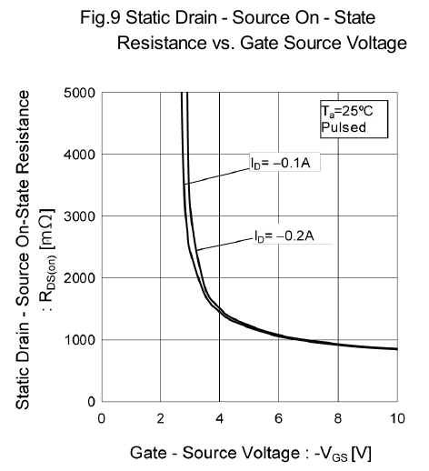
The best datasheet graph for that looks like this:
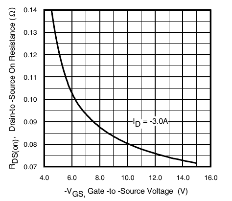
Sadly it isn't nearly as commonly published as it should be. The IRLML5203 datasheet does have one but it's also severely nerf'd, missing Vgs smaller than 4.5 V.
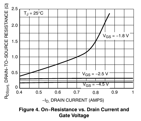
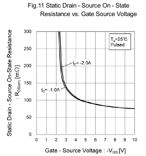
Here's a graph, from the OnSemi NTJD4152, showing the fading resistance when the gate voltage is too small. 2.5 V is fine but 1.8 V is a wreak waiting to happen.
@Rayman said:
See now that here VDD is 3.3V whereas usually using this part to control 5V...
How much current do you think the uSD is using at highest speed?
Max allowed is 200 mA in High Speed access mode. UHS can request more but we're not likely to ever be engaging UHS.
The IR datasheet is lacking detail below 4.5 V. There is a glimmer of hope in the Fig 1 graph that shows 3.5 V functioning okay ... but 2.7 V is a right-off. 3.0 V is probably what you want to target - Doesn't feel good to me.
You could drop the 1.8k resistor in the card detect down to improve the low voltage on Vgs a little more if you also drop the pull ups down to 10k, but using a low Vt and low Rds p-channel MOSFET is more ideal. Many pFETs are available in multiple packages, it might be safer just to find another part that suits your board layout and use that. Using one that is marginal may result in random instabilities and strange behaviours under high speed load when the voltage delivered to the SD card drops, and you wouldn't want that. For just something you want to mess around with at home you might be okay as is if it seems to be working, good luck.
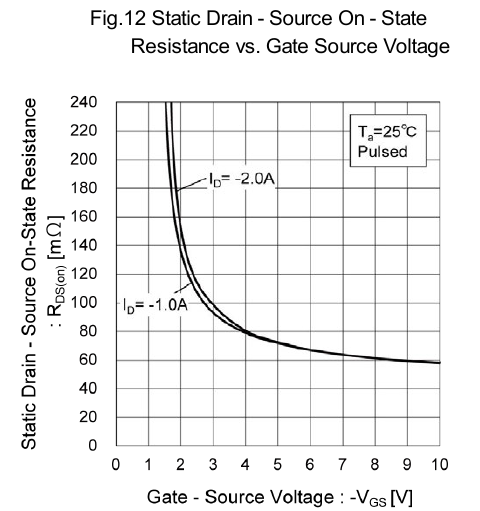
Okay, here's something interesting. Two parts from Rohm, the RQ5A020ZP and the RQ5C020TP. Same case, same general specs except the max Vds is 12 Volts for the former and 20 Volts for the later. And there is the respective differences accordingly, one being the max Rds is naturally higher for the 20 Volt part.
The interesting part, which probably is a natural characteristic of MOSFETs too, that I've picked up here is the gate turn-on Volts also shifts lower with the lower max Vds.
First the the 12 V part (RQ5A020ZP).
And the 20 V part (RQ5C020TP). The knee is maybe 0.7 V higher.
Ah, I think I know how that works. The lowered max Vds along the channel also lowers the punch-through risk. So the gate insulation can then be manufactured thinner too. And I presume a closer gate will be more effective with a lower Vgs.
Way back then, Circuitsoft recommended this part in the same footprint I used as a better alternative in case of issues as it had a lower Rds defined for lower Vgs voltages... NTJD4152P
As we didn't encounter issues under load I didn't change it on my boards, but in any production board I would recommend an improved part choice so if Parallax / @VonSzarvas ever decide to take up a similar design and produce boards I would recommend looking at something like that.
Ha-ha, it works! Not needing any power switch circuit allowed me to quickly wire up a full sized SD slot so I can now test full sized SD cards too. I have one 2 GB card, I got with the camera, that will allow me to work out the kinks with SDSC type cards.
Oops, I wrote to my camera card. Amazingly it seems to be intact still. The filesystem metadata is still there. So, it must have defaulted to 512 byte blocks or something.
It actually doesn't make sense because the driver has no scaling from blocks to bytes. Yet that is supposed to be required. And the card surprised me in another way too. It responds as a v1.0 type card. I had to ignore the CMD8 fail and modify the ACMD41 argument to get the init routine to pass. I got a surprise when that's all it took to spring to life and started writing files.
CID register is reporting card as made in 2007. And has the correct OEM/Manufacturer IDs.
EDIT: Oh, duh, I did add the block to byte scaling not that long ago. Well, I guess that works then.
EDIT2: I got to fix up a few things now though. The driver doesn't understand the v1.0 CSD register.
@Rayman said:
cant cycle power without the 1.8k resistor right?
It could. The driver could control it without that 1k8 Card-Detect pull-down. It would act a little differently because it'd be actively enabling the power all the time. Whereas at the moment the driver just momentarily turns the power off. The pull-down does most of the work.
Btw: is the driver checking this for presence of sd?
The driver is now set to abruptly fault from within the ACMD41 repeat cycle if any attempt doesn't get a response from the card. Previously it just kept retrying if there wasn't a response. This solves a new problem with v1.0 cards where neither CMD0 nor CMD8 have a response - With it then it falling on the ACMD41 wait-for-ready loop to determine if a card is even present.
@evanh said:
Ha-ha, it works! Not needing any power switch circuit allowed me to quickly wire up a full sized SD slot so I can now test full sized SD cards too. I have one 2 GB card, I got with the camera, that will allow me to work out the kinks with SDSC type cards.
Comments
Yeah I believe when an 8 pin group is available on an accessory header board the schematic is probably about as useful as possible while not being overly complicated. One FET, two LEDs and some resistors and caps, not too hard to make. Power LED comes on when card is inserted. Activity can be made to light up in sympathy with data or for debug use. Parallax could replicate it and sell them one day with any luck.
At what point would one power cycle due to failure of sd?
Mount ?
Fopen?
Failure to do the card init could be useful to try a reset/retry - I guess that is during the mount operation. This may happen if the card is stuck in SPI mode and can't get back to SD mode or vice versa? (one way is possible to transition without a reset, can't recall which works which doesn't offhand).
One issue might be the delayed init. That is an option that can be turned off right?
Or maybe power cycling should be part of unmount? @ersmith seems to call this first…
Sometimes I'll pass -1 to a driver if don't want it to use a pin. Might be nice here for power and led pins. Somebody (not me) might want to not use them in the driver itself...
That's a good idea. I'll add that.
Unmount just clears the pin modes. Power cycling gets done at next init.
At the moment, the driver just quits on init error. The filesystem seems to retry once, so up to two attempts of init before it too gives up.
Done. Both the Activity LED Pin and the Power Switch Pin can be set to -1 so they won't be used.
The whole card-detect-power-cycle sequence gets skipped when PIN_POW = -1. If the SD Card is already operating normally then it has no issues. The init sequence attempts a CMD0 after the power-cycle anyway, so nothing else was needed.
More coding was needed for the LED control, since that is embedded in the block read/write routines. Each case needed an if() statement placed inline.
How important is the pullup resistor value? Think 10k would be just as good?
Hmm, the power switch is the critical situation. 10 KR is fine for everything else. Those p-FETs kind of need every bit of gate volts they can get. The lower the pull-up resistance is the worse it becomes for the gate volts.
Here's some details - https://forums.parallax.com/discussion/comment/1545314/#Comment_1545314
Circuitsoft recommends using a FET more suited to small gate voltages. That would be good idea and would give more tolerance to using 10 kR pull-ups.
PS: Another thing to pay attention to with MOSFETs like this is possible damage from static discharge. They do need to be well shielded if the PCB ever becomes exposed to high voltage static. I was regularly replacing such a transistor type many years ago inside the control panel of the light-bar of police cars. It was presumed to be purely from operators touching the switches and a static spark jumps from their fingers. Now I think about it, that would've been an extreme case of ground bounce that I get so concerned about. The MOSFET that regularly failed was associated with the linking cable up to the light bar on the roof.
EDIT2: Ah, that OnSemi NTJD4152P part that Circuitsoft recommended also has extended static protection. A good part to use for simple switch control like this.
Hmm... One I'm testing with is IRLML5203. Guess should test with 10k. Easy to do as currently using two 10k in series...
The best datasheet graph for that looks like this:
Sadly it isn't nearly as commonly published as it should be. The IRLML5203 datasheet does have one but it's also severely nerf'd, missing Vgs smaller than 4.5 V.
Here's a graph, from the OnSemi NTJD4152, showing the fading resistance when the gate voltage is too small. 2.5 V is fine but 1.8 V is a wreak waiting to happen.
See now that here VDD is 3.3V whereas usually using this part to control 5V...
How much current do you think the uSD is using at highest speed?
Max allowed is 200 mA in High Speed access mode. UHS can request more but we're not likely to ever be engaging UHS.
The IR datasheet is lacking detail below 4.5 V. There is a glimmer of hope in the Fig 1 graph that shows 3.5 V functioning okay ... but 2.7 V is a right-off. 3.0 V is probably what you want to target - Doesn't feel good to me.
Can probably find another part, but proof is in the pudding right? It is working…
You could drop the 1.8k resistor in the card detect down to improve the low voltage on Vgs a little more if you also drop the pull ups down to 10k, but using a low Vt and low Rds p-channel MOSFET is more ideal. Many pFETs are available in multiple packages, it might be safer just to find another part that suits your board layout and use that. Using one that is marginal may result in random instabilities and strange behaviours under high speed load when the voltage delivered to the SD card drops, and you wouldn't want that. For just something you want to mess around with at home you might be okay as is if it seems to be working, good luck.
Okay, here's something interesting. Two parts from Rohm, the RQ5A020ZP and the RQ5C020TP. Same case, same general specs except the max Vds is 12 Volts for the former and 20 Volts for the later. And there is the respective differences accordingly, one being the max Rds is naturally higher for the 20 Volt part.
The interesting part, which probably is a natural characteristic of MOSFETs too, that I've picked up here is the gate turn-on Volts also shifts lower with the lower max Vds.
First the the 12 V part (RQ5A020ZP).
And the 20 V part (RQ5C020TP). The knee is maybe 0.7 V higher.
Ah, I think I know how that works. The lowered max Vds along the channel also lowers the punch-through risk. So the gate insulation can then be manufactured thinner too. And I presume a closer gate will be more effective with a lower Vgs.
Here's the datasheet for the part I used.
https://fscdn.rohm.com/en/products/databook/datasheet/discrete/transistor/mosfet/um6j1ntn-e.pdf
By doubling up the dual fets in parallel, it effectively reduced the Rds by half. The voltage drop when measured under a ~145mA load was marginal but measurable at 160mV.
Way back then, Circuitsoft recommended this part in the same footprint I used as a better alternative in case of issues as it had a lower Rds defined for lower Vgs voltages... NTJD4152P
As we didn't encounter issues under load I didn't change it on my boards, but in any production board I would recommend an improved part choice so if Parallax / @VonSzarvas ever decide to take up a similar design and produce boards I would recommend looking at something like that.
Noted. Thank you.
Ha-ha, it works! Not needing any power switch circuit allowed me to quickly wire up a full sized SD slot so I can now test full sized SD cards too. I have one 2 GB card, I got with the camera, that will allow me to work out the kinks with SDSC type cards.
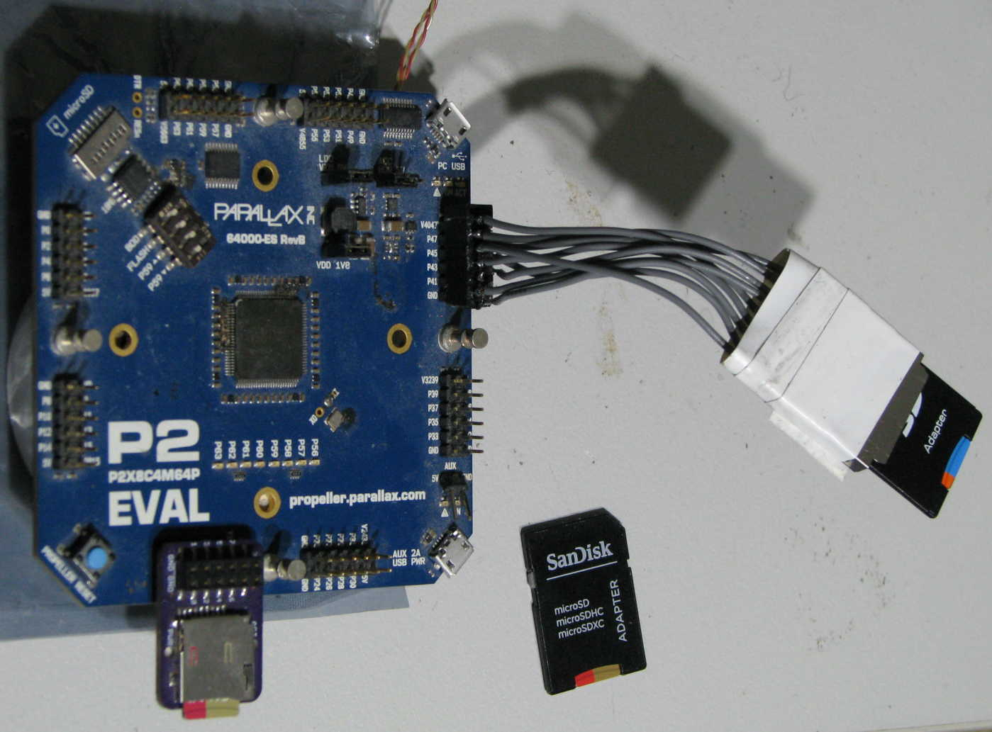
Oops, I wrote to my camera card. Amazingly it seems to be intact still. The filesystem metadata is still there. So, it must have defaulted to 512 byte blocks or something.
It actually doesn't make sense because the driver has no scaling from blocks to bytes. Yet that is supposed to be required. And the card surprised me in another way too. It responds as a v1.0 type card. I had to ignore the CMD8 fail and modify the ACMD41 argument to get the init routine to pass. I got a surprise when that's all it took to spring to life and started writing files.
CID register is reporting card as made in 2007. And has the correct OEM/Manufacturer IDs.
EDIT: Oh, duh, I did add the block to byte scaling not that long ago. Well, I guess that works then.
EDIT2: I got to fix up a few things now though. The driver doesn't understand the v1.0 CSD register.
@rogloh cant cycle power without the 1.8k resistor right?
Btw: is the driver checking this for presence of sd?
It could. The driver could control it without that 1k8 Card-Detect pull-down. It would act a little differently because it'd be actively enabling the power all the time. Whereas at the moment the driver just momentarily turns the power off. The pull-down does most of the work.
Yes.
The driver is now set to abruptly fault from within the ACMD41 repeat cycle if any attempt doesn't get a response from the card. Previously it just kept retrying if there wasn't a response. This solves a new problem with v1.0 cards where neither CMD0 nor CMD8 have a response - With it then it falling on the ACMD41 wait-for-ready loop to determine if a card is even present.
Random SD cards from old digicams, my beloved
Also that's a really dirty P2EVAL
And it's worse than it looks. Jumper'd blown USB switches, and half the headers have faulty I/O.
I've got a fresh Eval board sitting on the sidelines when I need it.
Seems the pfet actually been using most is this one:
SSM3J327R
@evanh Think this one will meet your approval, right?