

Ratiometric potentiometer input
 ManAtWork
Posts: 2,369
ManAtWork
Posts: 2,369
I'd like to have a knob on the front panel of a controller where the user can tune a proportional value between 0 and 100%. I know, all those "modern" products (radios, scopes...) use those encoder type input devices with 16 or 64 positions per revolution. But I like the feel and touch of a real potentiometer much better. It has a hard stop at 0 and 100% and an optional "snap" at the 50% center position. Or you can put a pointer on the knob and a scale on the panel and tell exatly where you are without looking at some other display.
The P1 has no built in ADCs so the simplest solution is to use an RC decay circuit to measure resistance.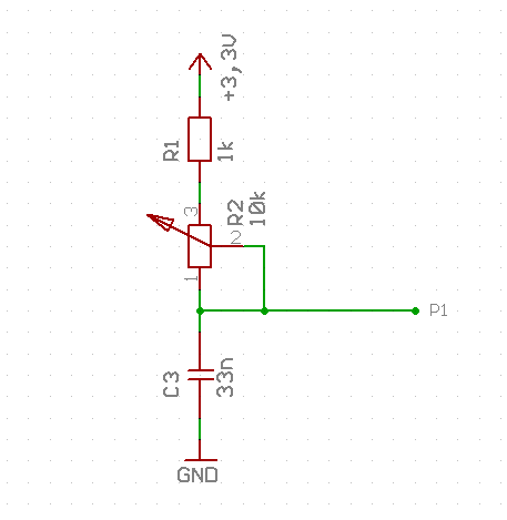
This requires only one pin. The strategy is
1. discharge the cap by driving the pin low.
2. let the pin float and measure the time until the input becomes high
The time is proportional to the resistance. The problem is that the capacitance has a tolerance of 10% and the full scale resistance of the pot also has 10 or even 20%. The time also depends on the input threshold voltage, so the overall tolerance is >20%. It would require some sort of calibration to reliably detect the 0, 50 and 100% positions.
My next idea was this circuit: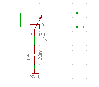
1. drive both pins low
2. wait until the cap is discharged (takes longer, >5RC time constants, say >2ms)
3. drive pin P2 high, let P1 float
4. measure the time t1 until P1 input becomes high
5. drive both pins low, wait until discharged
6. drive pin P1 high, let P2 float
7. measure the time t2 until P2 input becomes high
The position of the pot wiper can be calculated as t1/(t1+t2). As this is truly ratiometric the tolerances of R and C should have no influence on the result. There are some imperfections like P1 and P2 don't have exactly the same threshold voltage. But it should be at least much better than the first circuit. However, now we need two pins.
Or we could do it this way: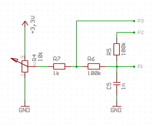
P1 and P2 act as sigma/delta ADC with a counter in feedback mode. P3 can be used for self-calibration by driving it low or high for calibration or let it float for measurement. The internal resistance of the driver of P3 together with R7 and R4 add some error. The calibration does not pull R6 exactly to ground or to 3.3V. But most of this error can be compensated by using an equivalent current source model. Disadvantages are: 3 pins required, much more complex calculations.
Of course, it would be much easier to just take a P2 and forget about all those hassles. But I like challanges, especially using clever software to replace complex or expensive hardware. ![]()
Does anybody have better ideas?
Nice to have would be...
- around 1% accuracy and 10 bits resolution
- 10 or 20 samples per second
- no calibration procedure where the user needs to turn the knob. Automatical calibration once at startup or on-the-fly are OK.
Comments
Easy...get a RPi Pico (dirt-cheap) as a slave (I have 4 as expanders for my P2)
Craig
Challenges, clever software, complex or expensive hardware...
Have a look at the ef8bb5 series of SiLabs 8051 micros. You'll get wat you want and more and all that at 5V too.
Just a thought.
Maciek
Seriously? I ask for a hardware hack in the propeller forum and all I get is the advice to use a different µP?
I think I should quit.
NO! Inventing and creating is fun. Production and testing isn't. I won't put another processor on my board. Not only because of the money and possible sourcing problems. I just don't want to program them. It adds another step to the test procedure. I could also use schematic #1 and do a calibration step teaching in the 0 and 100% positions instead.
I'm thinking out loud here: could you use a variable inductor instead? One with two coils (one driven by a signal, the other "listening") and a variable core?
Perhaps something like this sigma dalta ADC
https://github.com/parallaxinc/propeller/tree/master/libraries/community/p1/All/Single Pin Sigma Delta ADC Driver v1
You asked for "a better idea"
There is nothing more readily available today than the RP2040.
For me, zero learning to be done because I'm not a snob and fully embrace the amazing MMBASIC interpreter. We are talking four ADCs @125KHz or individually @500KHz.
Flash storage with far more sophistication than what you did for the P2 and a complete filing system for an SD card.
Already support for many displays and touchscreens.
Why waste precious prop resources on something so mundane.
Craig
Ha ! That's what happens when you leave too much room for the interpretation of the problem description
Besides, I love to throw some sand in to the gears. One gets things clarified instantly.
I'd go with the No.2 solution you presented. Looks like a fair compromise.
I don't think I've ever seen a digitally-read pot where the full range is actually used. Always has some deadzone either end. Though if you want a dial such that the center position means 50%, that's a bit naff. Perhaps the calibration of such a thing would drift with age, anyways. Analog joysticks calibrate their pot/ADC center point by assuming the stick is centered on power-up, but that doesn't work for a dial pot.
I used your first circuit on the EFX-TEK AP-16+ and AP-8+ audio players. The following method is used to read the volume pots. I did a bit of empirical testing to get scale values. It worked nicely for what it needs to do.
ManAtWork,
It's good to see the differences laid out clearly like that. Nice write up.
I certainly wouldn't be throwing extra micro-controllers, not even cheap ones, at the job unless it's also managing a readout and buttons. Then I'd be using encoders instead of pots.
Machine control: I like my watchdogs. My servo-loop cog provides a heartbeat to 3 of my RP2040s. Their internal watchdogs are refreshed by this and if they don't get refreshed, all 3 of them drop their DMRs (dead-man-relays).
Craig
Safety circuits ain't got a lot to do with user input.
PS: I don't count an E-Stop as user input.
A small dead zone at the low and high end is OK. But if the user sets, say 25%, shuts down the machine and powers it up the next day it still has to be at 25%. So no center point calibration is possible assuming that the (for joysticks spring centered) startup position is 50%. This is also the reson why I don't want an encoder. It would require to store the current position in permanent memory.
I think I'll take circuit #2 and see how accurate it is. I may add another dead zone in the center. If 48..52% counts as center it's not too irritating to the user and 2% tolerance would be acceptable.
I like the concept. Please let us know how it works out.
Thanks,
-Phil
If more analog inputs are needed this can be done the P1's way using one feedback and multiple comparator inputs. I did it here: https://forums.parallax.com/discussion/102534/multi-input-adc#latest
Unfortunately the ASCII-Art circuit is no longer readable. But I may find a screenshot of the design if needed.
I have some pins left over so I decided to add feedback resistors.
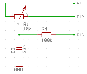
This way I can measure the threshold voltages of the input pins (P1L/P1R) by using the center pin (P1C) as sigma delta feedback. The auto-calibration can be done once at startup and is independant of the wiper position. It provides scaling factors for the RC time measurement and shopuld improve the overall accuracy.
ErNa's trick to use a single feedback pin for multiple ADCs cannot be used here, unfortunatelly, as it would cause crosstalk. But as I only need to read out two potentiometers and have lots of spare pins that's not a problem.
That's not ideal!
I've added an image of the ASCII art to your first post in that thread. (And have added that example to the forum todo list - curious how the formatting is mangled even after the font/encoding is fixed, hence the image attachment for now.)
Took me a while to realise that that circuit relies on only metering one ADC at a time. And when switching between them needs a settling time before taking the measurement of the selected input. Certainly had me scratching my head, for a bit, as to how one input didn't feedback into the others. Of course, it does. Which is why the settling time is needed.
Following up on a sigma/delta approach, would the following ideas work? The first uses counters to drive the ends of the potentiometer with a pair of external mosfets, and the second uses a tight PASM loop to drive internal Prop mosfets between output and open states. Both ideas use integration on the capacitor attached to the wiper to feed a sense pin.
I haven't thought about calibration, and the end-to-end resistance of the potentiometer is a problem. The two 10k resistors are added to keep the action centered.
"But I like challenges, especially using clever software to replace complex or expensive hardware." +1, the Prop 1 counters are a Swiss Army Knife.
Yes, the problem is the tolerance of the end-to-end resistance of the potentiometer which is +/-20% for most brands. And you can't assume that the sense pin (P2) has a threshold of exactly 1/2 the supply voltage. So you'd need to calibrate both the range (poti end-end vs. 2 x 10k fixed resistors) and the center position. The operator of the production test has to manually move the knob to the center and both end positions. That's what I try to avoid. If calibration is required it should be done fully automatical.
I have to apologise for my criticism of all your ideas. ( @Mickster , @Maciek , @"Tracy Allen" , @MAElektronik , @JonnyMac ...) It may sound like I'm a bit picky. Why do I ask if I prefer my own ideas more... I thought there was an easy solution that I just haven't known. But it seems that it's more complicated than I thought.
I've made a PCB with the circuit of post #17. It takes some time until it's tready and I can test it. Thanks for all the feedback.
@ManAtWork Heck, no need to apologise, I for one am envious of your skills/abilities.
And I like the approach.
Ask around. Evaluate advices. Make your decission based on your judgement. Nobody gets inside ones head. Apologies are out of order here. Fingers crossed you'll be proved right with the solution of choice.
How many of these are you making ?
Have you checked the physical snap at 50%, for resistance balance ? - pots also have non linearities, so an exact 50% resistance ( which post #17 can sense nicely) may be off from the "snap"
That ratiometric approach should be better than 1% pin threshold matched, but getting 10 bit resolution over cables to a machine could be a problem ?
I do not see any ESD resistors between the pot and the MCU ?
Another 3 terminal design to consider could be the classic oscillator, this has lower frequencies at the pins / cables than a delta-sigma feedback design.
In your case, you swap R1,R2 (arms of the pot) in SW, and measure the periods.
If you swap ends on the 'zero cross' there is no need for any 'wait until the cap is discharged' as you know the voltages at that balance point.
You might add ~1k to the pot ends, for ESD and to limit peak currents.
The simplest 3 component oscillator uses R1 to isolate the annoying CMOS clamp diodes, but adding a C2 to GND (=C1) can drop the peak dV at that node, so the clamp diodes are never seen.
I'll make ~100/year. I know, that volume doesn't justify spending $1000 on development&research to save $0.10 per unit. But if it's possible I'd like to make a "clean" design that I can re-use later as "known good module". If not I can always fall back to something requiring calibration.
I hope ESD is not an issue. The propeller will be close to the pot, no cables and connectors in between.
I do very much like to see the variety of the possible solutions. Keep it simple but not too much so. Constructive criticism, alternatives, and reality checks welcome!
If sense of the centre detent placement is important, you could get a good supply of chosen quality pots in, and check the variation in resistance match, to find out if that's tight enough to avoid calibrate-to-pot ?
Another idea for ratio reading, is to use a 4046 style oscillator like this.
Here the cap is shared, and each arms rise or fall time alternately measured. The cap is 'shorted' to start, which is fast, and one side released whilst the other side remains at GND or VDD
If you capture both rise and fall times, any pin threshold variation is reduced.
                +------+----/\/\/\--[PinA
                | 10k  |     esd
               [P]     |
 +---/\/\/\----[o]    ===
      Rlim     [t]     |
      330R      |      |     esd
                +------+---/\/\/\---[PinB
addit:
Then the above is likely fine.
For situation with significant cable runs and noise, another option is to do the Pot to Digital at the pot end of the wiring
A CMOS 555 can do this
Remote Wiring : pot to digital at the remote end Ideal Diode ( PFET or RET PNP) +-------|<|---------------------+ | +-----------+ | | VCC--o|RSTN VCC|---|---+---> Vcc | | | | | | |CV | | === Cd | | | | | | +--|TRIG | | GND [P] | | OUT|---+-------> 50% Duty at Mid pot [o]-/\/\--+---+--|TH | Opto isolation optional [t] Rmin | | Disc|---+ | === Ct | CMOS555 | | +----> GND | | | Monostable| | | | GND +-----------+ | GND +-------------------------------+I finally made a PCB with the circuit in post #17. It works quite well.
The ReadPoti() function return a value between 0 and 1000 which seems to be fairly linear and without noise. I think calibration is not necessary. The absolute error of the poti center position is larger than the error of the Propeller hardware. There is a small hysteresis caused by "elasticity" of the center notch causing it to give different results depending on if the center position was aproached from the left or right direction. I've also sampled 8 different potentiometers and their center points are within 48 and 52% of the total resistance.
Another proble is that the spin code has a minimum delay time of ~1300 clocks for the WAITPEQ command. I have to write code in assembler to be able to egt valid results for <10% and >90%.
The assembler version works quite well even without calibration