

Multi-Input ADC
 ErNa
Posts: 1,862
ErNa
Posts: 1,862
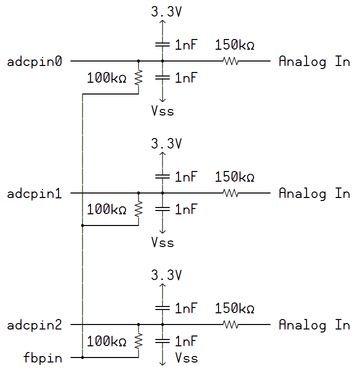
Sometime there is need to measure more than two slowly changing analog values. This obviously can be done:
There is one feedback pin which can drive as much 100 k resistors in parallel and more than one input can be used as comparator inputs. The active inputpin can be selected on the fly and after waiting some time, the selected analog input stabilizes and is not influenced by the other inputs. Following just my simple test software in Spin.
[code]
' Test MUX-AD-Converter: feedback Control Output 23, Inputs: 20, 21, 22
ADCOutPin := 23
ADCInPin := 22
DIRA[noparse][[/noparse]23]~~ ' Pin 23 Control Output
CTRA := %01001_000 << 23 + ADCOutPin << 9 + ADCInPin
FRQA := 1 ' Modus f
ModEdit: Add image of ASCII art
3.3V
                             
                            1nF  150kΩ
          adcpin0 ────────┳──╋─────────── Analog In
                     100kΩ 1nF
                   ┌──────┘  
                   │        Vss
                   │
                   │        3.3V
                   │         
                   │        1nF  150kΩ
          adcpin1 ─┼──────┳──╋─────────── Analog In
                   │ 100kΩ 1nF
                   ┣──────┘  
                   │        Vss
                   │
                   │        3.3V
                   │         
                   │        1nF  150kΩ
          adcpin2 ─┼──────┳──╋─────────── Analog In
                   │ 100kΩ 1nF
            fbpin ─┻──────┘  
                           Vss
There is one feedback pin which can drive as much 100 k resistors in parallel and more than one input can be used as comparator inputs. The active inputpin can be selected on the fly and after waiting some time, the selected analog input stabilizes and is not influenced by the other inputs. Following just my simple test software in Spin.
[code]
' Test MUX-AD-Converter: feedback Control Output 23, Inputs: 20, 21, 22
ADCOutPin := 23
ADCInPin := 22
DIRA[noparse][[/noparse]23]~~ ' Pin 23 Control Output
CTRA := %01001_000 << 23 + ADCOutPin << 9 + ADCInPin
FRQA := 1 ' Modus f
ModEdit: Add image of ASCII art
718 x 762 - 21K
Comments
Post Edited (Rayman) : 4/2/2008 10:30:38 AM GMT
CON
  ADCNmb    =  3  ' Number of inputs to scan
  ADCOutPin = 23  ' Control output in for ADC
  ADCInPin  = 20  ' First input Pin, ADCNmb consecutive pins


DAT
  ADCIdx      long  0     ' Index of Input
  ADCMux
  ADC_MuxV0   long  0     ' value of input 0 during measuring time
  ADC_MuxV1   long  0     ' and so on
  ADC_MuxV2   long  0     '
  ADCStrtTime long  0     ' start time last conversion  ADC_Values             ' analog values  normalized
  ADC_Value0  long  0
  ADC_Value1  long  0
  ADC_Value2  long  0


  if  cnt - ADCStrtTime >  clkfreq/50 ' every second fifty times, if you like

     ADC_Mux[noparse][[/noparse]ADCIdx]     := phsa - ADC_Mux[noparse][[/noparse]ADCIdx]
     ADCStrtTime         := cnt  - ADCStrtTime
     ADC_Values[noparse][[/noparse]ADCIdx]  := ADC_Mux[noparse][[/noparse]ADCIdx] / (ADCStrtTime /1000)
     ADCIdx              := (ADCIdx+1) // ADCNmb
     CTRA := %01001_000 << 23  +  ADCOutPin << 9  + ADCInPin+ADCIdx  ' activate next control input
     ADC_Mux[noparse][[/noparse]ADCIdx]     := phsa
     ADCStrtTime         := cnt
This gives quite stable values and the module can be integrated into a loop with varying runtime. I didn't think about to optimise the memory consumption, only try to make it working
▔▔▔▔▔▔▔▔▔▔▔▔▔▔▔▔▔▔▔▔▔▔▔▔