

Cluso's P2 RetroBlade2 Single Chip Computer (small stock and build to order)
 Cluso99
Posts: 18,071
Cluso99
Posts: 18,071
Cluso's RetroBlade2 Single Chip Computer (small stock available for new orders/payment) - title renamed 19Jul2021
Discussion for using your RetroBlade2 starts/continues here
forums.parallax.com/discussion/172556/clusos-retroblade2-your-board-s-have-arrived-so-what-to-do-next/p1?new=1
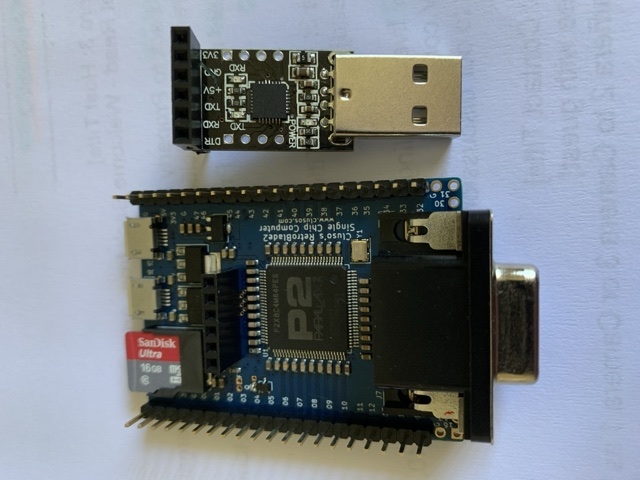
Cluso's P2 RetroBlade2
* PCB 1.6"x2.2" 2 layer ENIG 1.6mm FR4
* P2X8C4M64P chip of course (all new board use Rev C chips)
* 20MHz xtal
* Requires 5V regulated input (from one of: headers, microUSB, or USB/TTL header)
* 3V3 1A LDO SOT-89 regulator
* 1V8 generated by series 3V3 1A LDO SOT-223 to 1V8 1A LDO SOT-223
* Proper bulk and bypass capacitors
* Transistor reset circuit (as per P1) configured with solderable link
* microSD socket (microSD card not supplied) - can boot direct from microSD without Flash
* Two microUSB sockets - for power / keyboard / mouse (cables available from fleabay for ~$1.50)
* P00-15 brought out on 1x20pin 0.1" header
* P16-31 brought our on 1x16pin 0.1" header (under optional included VGA connector)
* P32-47 brought out on 1x20pin 0.1" header
* P48-49 brought out on microUSB connector
* P50-51 brought out on microUSB connector
* P52-57 brought out on tiny 0.4mm thru-hole pads (will take single AWG30 kynar wire-wrap wire)
* P58-61 used internally for microSD and (optional) SPI Flash
* P62-63 brought out on 1x6 0.1" header (serial port) for Reset/SerialOut/SerialIn/5Vin/Gnd/nc - compatible with cheap CP2102 USB/TTL 6pin (not supplied - fleabay ~$1.50)
* Note: P27-31 also connects to VGA socket (if fitted) for video/LCD (connector overlays the P16-31 header)
* Optional SOIC-8 footprint on underside for Flash W25Q32JVSIQ/W25Q64JVSIQ/W25Q128JVSIQ/S25FL256 (4/8/16MB/32MB Flash)
* Through hole parts supplied but not fitted/soldered
* Can run my P2 OS and Z80/CPM emulation
* Inline 0.1" pitch headers fit breadboards.
Notes:
* The regulators will likely self-limit to somewhere in excess of 500mA. Switchers are not used. I have tiny heatsinks ordered (set for Raspberry Pi) to try them out as the reguators can handle 1A if they can be cooled. Same goes for P2.
* The photo shows the VGA connector fitted but it comes unsolderd.
* A 1x2pin 0.050" header/link enables the onboard 10K pullup resistor for booting from the (optional) Flash chip
Flash
Flash is an option. I will be fitting the 32MB S25FL256 flash chip to new orders. Some other brands require a modification to connect the WP and HOLD pins to 3V3.

New Orders...
Updated: 13-April-2021
New orders will use P2 Rev C chips. If you order the Flash option I will fit the S25FL256 32MB version.
Please post orders in this thread or email me
cluso -at- bluemagic -dot- biz (replace the -at- and -dot- and especially note the .biz)
Please let me know your country, and if the Flash option is required. These are the only two pcb options.
PayPal Payment will be via PayPal in USD to cluso -at- bluemagic -dot- biz (replace the -at- and -dot- and especially note the .biz)
Please ensure payment is in USD as PayPal tries really hard to convert the currency so they can maximise their commission!
RetroBlade2 without Flash USD $40 (excluding postage) each
RetroBlade2 with Flash (now 32MB S25FL256) USD $45 (excluding postage) each
USB-Serial converter USD $2.50 (excluding postage) each. I have a small number bought during a price surge.
Postal charges have surged because Australia Post have blocked unregistered airmail and are forcing me to use postal courier which is now the cheapest from Australia. Cost is US$25 for up to 500g.
USA stock may be available via Publison (thanks Jim) for on-posting within the USA to you. The postage cost is US$5. Please check beforehand if there is USA stock.
Thru-hole parts (connectors) are not soldered, so your choice whether you solder VGA or pin headers.
I will include VGA connector as I have them anyway, unless weight becomes an issue as the VGA is 10g. The soldered pcb with VGA is ~30g plus packaging ~10g.
For USB Keyboard or Mouse I suggest something similar to this on fleabay. I bought a nicer white one a while ago but don't have a link.
https://ebay.com/itm/Micro-USB-Cable-Male-Host-to-USB-Female-OTG-Adapter-Android-Tablet-Phone-PDA-PC/122327249468?ssPageName=STRK%3AMEBIDX%3AIT&_trksid=p2057872.m2749.l2649
For USB downloading I use this, but you can get the better pricing (free shipping) from other sellers. Note the pinout aligns with the RetroBlade2.
https://ebay.com/itm/6Pin-USB-2-0-to-TTL-UART-Module-Serial-Converter-CP2102-STC-Replace-Ft232-Module/401092508083?hash=item5d62f9f9b3:g:2aQAAOSw0kNXhzR7
This post and the next have been updated with the latest info. There is only one pcb as it can do VGA and brings out P16-31 I/O on a 16 pin 0.1" header underneath the VGA connector.
KiCad passes all the design rule checks. It's all laid out now and the gerbers look good. Just need to panelise and send off (not panelised). Let me know below who wants them.
2020-10-13: Boards ordered - should be back in ~2 weeks
2020-10-26: Boards arrived - looking good
2020-10-30: First board built and preliminary testing - recognised by pnut, Rom Monitor and TAQOZ working to PST
2020-11-01: First board boots downloads from pnut and also boots from microSD")
2020-11-06: First board works with VGA, USB keyboard (garryj's code), and runs my Z80/CPM emulation (software not fully tested)
2020-11-10: Works with 4.0" LCD. Runs my OS (software not fully tested)
2020-11-26: Flash chips (some brands) require a pcb modification.
2020-11-27: First boards shipped
2021: New boards with Flash use S25FL256 and do not require the pcb modification.
Discussion for using your RetroBlade2 starts/continues here
forums.parallax.com/discussion/172556/clusos-retroblade2-your-board-s-have-arrived-so-what-to-do-next/p1?new=1
Cluso's P2 RetroBlade2
* PCB 1.6"x2.2" 2 layer ENIG 1.6mm FR4
* P2X8C4M64P chip of course (all new board use Rev C chips)
* 20MHz xtal
* Requires 5V regulated input (from one of: headers, microUSB, or USB/TTL header)
* 3V3 1A LDO SOT-89 regulator
* 1V8 generated by series 3V3 1A LDO SOT-223 to 1V8 1A LDO SOT-223
* Proper bulk and bypass capacitors
* Transistor reset circuit (as per P1) configured with solderable link
* microSD socket (microSD card not supplied) - can boot direct from microSD without Flash
* Two microUSB sockets - for power / keyboard / mouse (cables available from fleabay for ~$1.50)
* P00-15 brought out on 1x20pin 0.1" header
* P16-31 brought our on 1x16pin 0.1" header (under optional included VGA connector)
* P32-47 brought out on 1x20pin 0.1" header
* P48-49 brought out on microUSB connector
* P50-51 brought out on microUSB connector
* P52-57 brought out on tiny 0.4mm thru-hole pads (will take single AWG30 kynar wire-wrap wire)
* P58-61 used internally for microSD and (optional) SPI Flash
* P62-63 brought out on 1x6 0.1" header (serial port) for Reset/SerialOut/SerialIn/5Vin/Gnd/nc - compatible with cheap CP2102 USB/TTL 6pin (not supplied - fleabay ~$1.50)
* Note: P27-31 also connects to VGA socket (if fitted) for video/LCD (connector overlays the P16-31 header)
* Optional SOIC-8 footprint on underside for Flash W25Q32JVSIQ/W25Q64JVSIQ/W25Q128JVSIQ/S25FL256 (4/8/16MB/32MB Flash)
* Through hole parts supplied but not fitted/soldered
* Can run my P2 OS and Z80/CPM emulation
* Inline 0.1" pitch headers fit breadboards.
Notes:
* The regulators will likely self-limit to somewhere in excess of 500mA. Switchers are not used. I have tiny heatsinks ordered (set for Raspberry Pi) to try them out as the reguators can handle 1A if they can be cooled. Same goes for P2.
* The photo shows the VGA connector fitted but it comes unsolderd.
* A 1x2pin 0.050" header/link enables the onboard 10K pullup resistor for booting from the (optional) Flash chip
Flash
Flash is an option. I will be fitting the 32MB S25FL256 flash chip to new orders. Some other brands require a modification to connect the WP and HOLD pins to 3V3.
New Orders...
Updated: 13-April-2021
New orders will use P2 Rev C chips. If you order the Flash option I will fit the S25FL256 32MB version.
Please post orders in this thread or email me
cluso -at- bluemagic -dot- biz (replace the -at- and -dot- and especially note the .biz)
Please let me know your country, and if the Flash option is required. These are the only two pcb options.
PayPal Payment will be via PayPal in USD to cluso -at- bluemagic -dot- biz (replace the -at- and -dot- and especially note the .biz)
Please ensure payment is in USD as PayPal tries really hard to convert the currency so they can maximise their commission!
RetroBlade2 without Flash USD $40 (excluding postage) each
RetroBlade2 with Flash (now 32MB S25FL256) USD $45 (excluding postage) each
USB-Serial converter USD $2.50 (excluding postage) each. I have a small number bought during a price surge.
Postal charges have surged because Australia Post have blocked unregistered airmail and are forcing me to use postal courier which is now the cheapest from Australia. Cost is US$25 for up to 500g.
USA stock may be available via Publison (thanks Jim) for on-posting within the USA to you. The postage cost is US$5. Please check beforehand if there is USA stock.
Thru-hole parts (connectors) are not soldered, so your choice whether you solder VGA or pin headers.
I will include VGA connector as I have them anyway, unless weight becomes an issue as the VGA is 10g. The soldered pcb with VGA is ~30g plus packaging ~10g.
For USB Keyboard or Mouse I suggest something similar to this on fleabay. I bought a nicer white one a while ago but don't have a link.
https://ebay.com/itm/Micro-USB-Cable-Male-Host-to-USB-Female-OTG-Adapter-Android-Tablet-Phone-PDA-PC/122327249468?ssPageName=STRK%3AMEBIDX%3AIT&_trksid=p2057872.m2749.l2649
For USB downloading I use this, but you can get the better pricing (free shipping) from other sellers. Note the pinout aligns with the RetroBlade2.
https://ebay.com/itm/6Pin-USB-2-0-to-TTL-UART-Module-Serial-Converter-CP2102-STC-Replace-Ft232-Module/401092508083?hash=item5d62f9f9b3:g:2aQAAOSw0kNXhzR7
This post and the next have been updated with the latest info. There is only one pcb as it can do VGA and brings out P16-31 I/O on a 16 pin 0.1" header underneath the VGA connector.
KiCad passes all the design rule checks. It's all laid out now and the gerbers look good. Just need to panelise and send off (not panelised). Let me know below who wants them.
2020-10-13: Boards ordered - should be back in ~2 weeks
2020-10-26: Boards arrived - looking good
2020-10-30: First board built and preliminary testing - recognised by pnut, Rom Monitor and TAQOZ working to PST
2020-11-01: First board boots downloads from pnut and also boots from microSD
2020-11-06: First board works with VGA, USB keyboard (garryj's code), and runs my Z80/CPM emulation (software not fully tested)
2020-11-10: Works with 4.0" LCD. Runs my OS (software not fully tested)
2020-11-26: Flash chips (some brands) require a pcb modification.
2020-11-27: First boards shipped
2021: New boards with Flash use S25FL256 and do not require the pcb modification.
Comments
Schematic
And thanks to Ramon here is a nice pic of the board he received
Previously...
Gerbers looking good as are the paste pads under the P2
(my pcbs were just a tad behind my parts shipment and will be here Monday)
Probably would have been useful to put I2C (and maybe other connections) on the VGA connector but it might be too late as I would have to check everything again as I'm not comfortable to rely on KiCad yet.
BTW I checked the drill files for the slots - nice and simple
I really like the RetroBlade and would want one when it becomes available. Could you do a variant with HDMI and two RCA audio connectors?
I presume the audio is the same as P2 (ie RC plus isolation cap)? Presume a 4u7F or 10uF MLCC will work for the DC isolation and an RC of 1K and 100nF IIRC. Is more than one channel required?
I think an addon board that the RetroBlade could plug into might be better for these extras.
Of course it will plug into Peter’s 0.050” protoboard which i plan to offer too
Probably because it was far too expensive and we always had the dilemma of mixing thicker 100mil pins etc. I wasn't charged anything extra to get 3,996 holes drilled on each board.
Will you be offering these up on your website when they are ready?
* pcb now 2.2"x1.6" (was 2.0"x1.5")
* single pcb does both VGA and P16-31 on 0.1" header under the VGA connector
* adjusted the pitch of P0-15 and P32-47 to 1.5"
* VGA now uses the top pins P27-31 of the group with P27=VS
Now, you can solder the P16-31 header to just be on the underside of the pcb if you want to have both VGA and the header
Of course now I have to adjust the tracks and fills so this will take day(s)?
Same price - I'll ship both the 0.1" headers and the VGA connector. Through-hole parts will not be soldered.
R3 should be 1M
2020-10-13: First and second post updated with latest
BTW It’s been really quiet on the forums. What are you all up to?
BTW It’s been really quiet on the forums lately. What have you all been up to?
Can't wait to see.
I have noticed the crickets, but spammers behind the scene have not stopped. Off course Van and I shield you guys from all that noise.
Been busy with day job (bittersweet that...finally back into a rhythm, but less time for Prop play...isolation was good for that
Cheers
My pcb is 0.1” wider and 0.1” longer than the original P2D2.
Printing the paste frame now - holds the paste screen. I have printed a hinge too. Then i will need to align them both and mount on a bread board (for cutting bread).
Here is the frame with the hinge at the top (on the left here as the pic is rotated left). The stainless screen is mounted in the frame.
I’ve used these hinges before in my LCD to VGA screen and they work nicely.
Do you have a 3d printer? If not, what is your panel size(s) to 0.1mm accuracy and I'll make you the pcb mounting.
Your screen is already in a frame so will need to make some corners for positioning it.
The main problem is getting the pcb to fit snug in the frame when printed. The printer is not perfectly calibrated so some tweeking is necessary. The forth one I made finally fit perfectly. I'm printing my second screen frame now - expanded 100.1% and it's looking still a shade under-sized