

Model Railroad Engine Controller (PropActivityBoardWX, DualMC33926, Smoke, 18vDCC, WebPageControl,)
 Clock Loop
Posts: 2,069
Clock Loop
Posts: 2,069
Model Railroad Engine Controller that uses 3 Esp8266 WX modules plus a PropActivityBoardWX, DualMC33926, Smoke Maker, runs on 18vAC/DC/DCC (does not accept dcc commands, yet), total WebPageControl, Accelerometer in caboose, no caboose movement engine shutdown, timed start, fast start, emergency stop, throttle control, light control, smoke control.
V2.0 has better spin code and uses another wx module for dedicated webpage control.
Go to this link for 2.0 stuff.
https://forums.parallax.com/discussion/comment/1520649/#Comment_1520649
----OLDER VERSION 1.0
I absolutely love my new parallax powered train. (yoda: hmm, much have done you, far have gotten you. Train of light have you. mmmm)


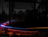

Train of light: https://forums.parallax.com/discussion/comment/1507321/#Comment_1507321
I am in the process of building a Model Railroad Engine Controller.
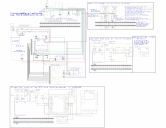
This first post will have all the updated schematic, code, and images.
It will be edited to include the latest code and design as I develop them.
The latest code with html control is attached to this first post.
https://forums.parallax.com/discussion/download/132130/NorthwoodsLogger.zip
The caboose code is now included and I changed the way the motor is controlled at bit.
(I have removed the ground side diode, fuses, to prevent ground floating)
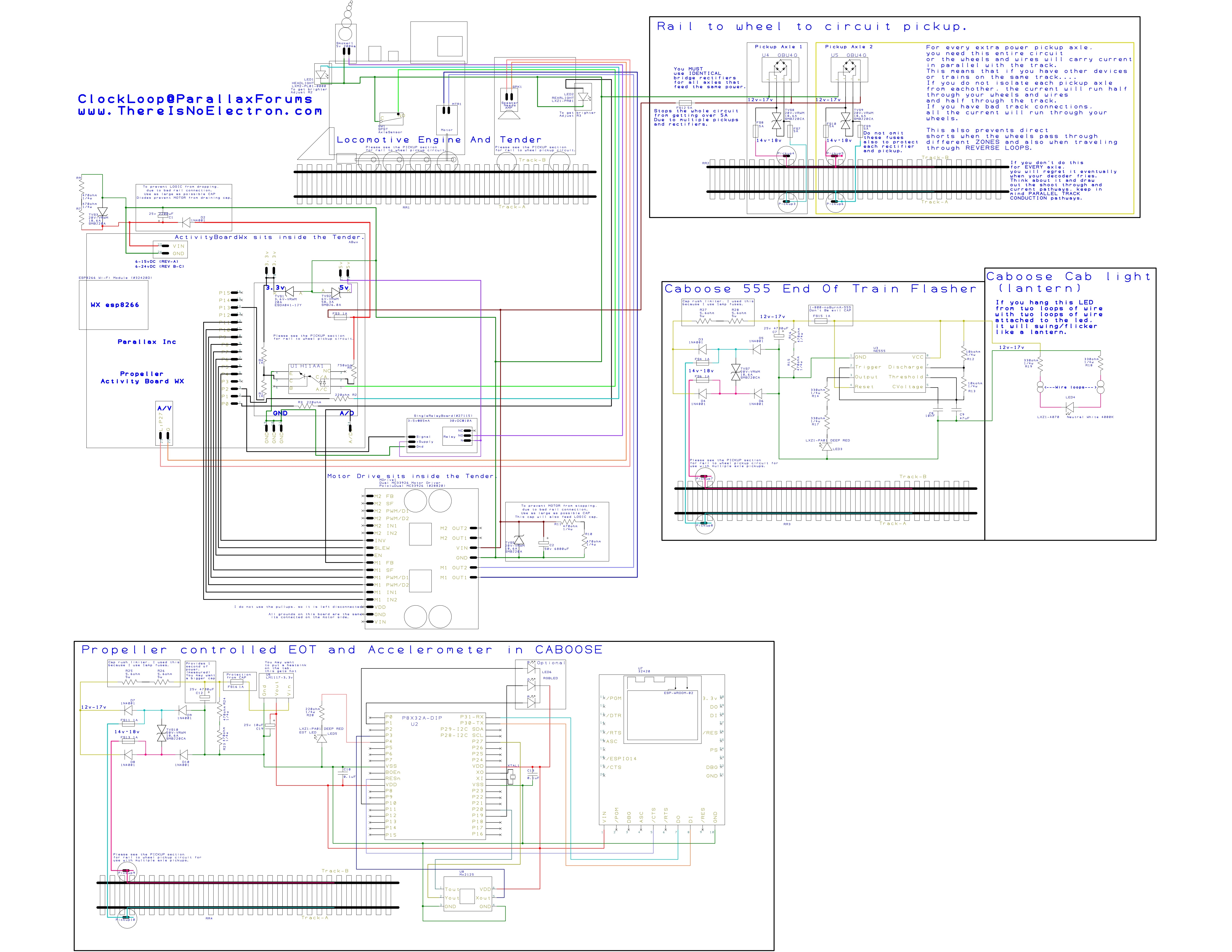
https://forums.parallax.com/discussion/download/132129/Northwoods Logger.pdf
Click link to get image bigger (3meg image)
https://forums.parallax.com/discussion/download/132128/Northwoods Logger.jpg
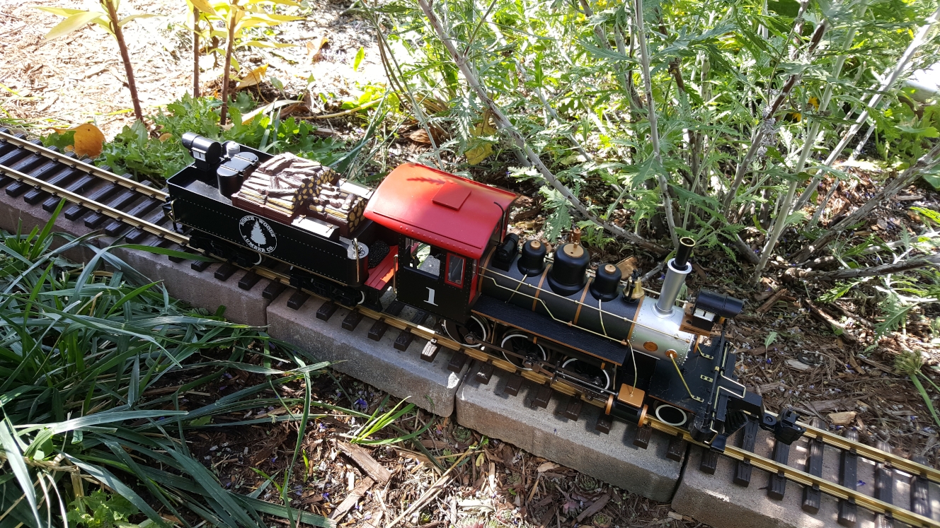
I purchased a North Woods Logger G-scale train set by Bachmann.
Everything about this train set sucks(mostly).
The track is cheap hollow steel, the engine smoke device leaks and is entirely too large, and barely puts out any smoke.
The leds are dim and a dull orangish color, the engine and tender circuitry is completely analog and useless.
The tender came with sound that literally sounds like someone banging a trashcan with a baseball bat,
(they used a hand full of discrete parts to make it), I'll give them an A+ for making a chuff sound with as little parts as possible.
The motor circuitry was almost nothing, it was powered by DC on the tracks.
I purchased a LGB 5v smoker, brass LGB track, bachmann is all about profit, made in china, and reduced costs as much as possible.
However their couplers are decent and look good, and cars look good, and engine frame/tender are ok, and all their wheels are metal, (surprisingly)
The tender has a large 1/2 watt 8ohm speaker which sounds ok with the proper amp and signal.
Currently the engine is only going to be controlled by a WIFI webpage that resides on a CODE customized Parallax WX Esp8266 WIFI device, connected to a ActivityBoardWX (rev1)
The track voltage is 14v and can be DCC because I am using a GBU4G full wave 4amp rectifier. (I need to include a larger capacitor than I currently use, so I just use 14vDC for now)
The motor drive is a Parallax Dual MC33926 board, which is fully wired for PWM control, status flag, and the current feedback is connected to the A2D chip on the ActivityBoardWX.
I currently only use 1 channel of the dual board, I will eventually use the other channel to power a cooling fan in the tender. (g-scale engines get hot in the outdoor sun)
The sound is also driven by the ActivityBoardWX, however I will need to find an amplifier, because it doesn't have enough power to push a 1/2 watt 8ohm speaker.
I pulled out the speakers from an old music cell phone, but they won't work due to a severe lack of power, with an amp of some kind, I can use the tender housing as a effective baffle.
Eventually I will drill small holes in the sides of the tender to use the cell phone speakers with, that is not my priority as I don't have an amp/circuit resolved yet.
The smoker was replaced with a LGB 5v smoker, which looks good quality, and doesn't look like it will leak, I will need to modify my setup to fit it in the smokestack, right now I just put it inside the smokestack sticking out.
The ActivityBoardWX is powered by 14v rectified track power (with the regular voltage drop from the rectifier).
I am currently using 1amp fuses during testing, but as I turn the motor, I will pop these, so I will need to use different fuses to power the motor board.
One of the axles inside the engine has a crude switch to sense the axle rotation for chuff sound, its just a copper metal flap pushing against the axle. The axle has 2 positions with conductive metal, so 1 full rotation of the axle will close the switch twice.
I wired the axle switch so that one side goes to ground, and the other goes to a H11AA1 optoisolators led, with a 1k resistor to 3.3v.
I will wire the optoisolator led to track voltage, because attaching it to 3.3v makes optoisolation pointless.
I just did this for testing, and the axle sensor SHOULDN'T ever touch track voltage, but bachmann made in china.. dont trust it.
I optoisolated the axle sensor for any possible shorts with track voltage of 14v, I don't want that going to my propeller pin.
The output of the H11AA1 goes to a prop pin with proper pull up resistor and a protection resistor going to the prop.
The headlight in the engine and the rear light in the tender will both be replaced with a Luxon Rebel LED with proper resistors to limit current, these are very bright at very low current, exactly what I want.
The rear light will be blue, and the headlight will be a white-orangeish color.
I would put a deep red rebel led into the firebox, and a white one in the cab, but I have run out of wires from the tender to the engine, I may just run another since its pretty easy, the wire bundle is already there.
I may one day use "EL wire" to make the engine look like the back to the future one, lol, but elwire uses seriously high voltage, so if I do that, it will be battery powered.
I would also only do that if I had other, better engines, like the big boy, and some diesel engines. (If wishes were fishes, we'd all live in the sea?)
The tender is the only electrical pickups for it all, which are copper metal pressed up against the metal on the axles, because I don't have enough wires to run electrical pickups from the loco also, but if it gets bad, i will wire those up also.
I am hoping a very large capacitor in the tender will solve that. I could replace the tender wheels with higher quality LGB ball bearing wheels that have nice electrical pickups with good connection points, but only if I need that.
The control of the engine is currently done using the Parallax WX esp8266 wifi device, and their open source code for it, I have modified it a bit so it looks more custom to the engine.
I don't have the code working at all for it yet, I am still learning how that happens, but the SPIN examples have left me in the dust, they are basically non-existant. The C code examples are excellent, and very thorough.
I am slowly learning how the C-code works and perhaps I can recreate it in spin, I am not sure how extensive it will be to make a spin file for the INCLUDE files they show in the c code to talk to the propeller.
The motor control in software is also something I will need to learn how to do, but that seems much easier than getting the WX to talk to spin code on the propeller.
I will also need to learn how to read the signal from the current feedback into the ActivityBoardWX A2D chip, I do not know if any examples exist in spin yet, I need to look into that.
I did some sound tests to play wave files from the microsd card plugged into the ActivityBoardWX. My tests went ok, but I quickly learned I will need to learn more to do multiple wave file output, if I want any kind of decent sound.
The idle, chuff, whistle, steam effects, brake squeel, coal shovel sound, wheel slip, and STACK TALK (very important), will all need to be able to be played simultaneously, so that means over 8+ wave files need to be accessed on the sd card and played independently, at any given time, potentially all of them at the same time. I don't know if the propeller is up to that task, I may need to limit that.
I plan to include more fuses and TVS diodes for an enhanced circuit protection, I am tired of my model railroad electronics frying.
This whole project was inspired by my problems with a brand name DCC command station going nuclear, up in smoke in less than 2 seconds simply because the manufacturer failed to include some of the most basic protection circuitry available.
for 10cents they could have saved a 250$ command station, a 60$ decoder/motor drive, and a 40$ sound unit. Seriously?
I gave up on the repair because after repairing 6 npn, and pnp transistors, the programming voltage still was not rising to the proper level, showing other damage that wasn't obvious.
You can read all about it here: https://forums.parallax.com/discussion/172039/can-ya-help-me-not-throw-250-into-the-trash-circuit-repair-help-request/
As far as DCC track control, I have not worked on this part, I may someday, but that would require more circuitry and extensive work in the SPIN program once I have all the above working I may start at.
But that would require me to create a Custom Command station of my own, this involves precise current sensors, powerful h-bridge, 10amp 14v power supply for it, and all the code involved, plus making a throttle device etc.
One problem with using wifi is I don't have a way to detect which block the train is in, for automation of train using JMRI control software.
However I have looked into multiple potential solutions to this and RFID might work, if I can get a RFID detector close enough to the tags that would be under the track.
I do not know if the track brass that has 14v dc would affect the RFID signal, I will need to do more testing to find out, and I have read some attempts by others to boost the range of RFID...
Using opto sensors for track block detection might work if the (IR) sensor is on the tender looking down at a reflective material of some sort, and even possibly using neodymium magnets under the track with reed switches on the tender trucks.
I would need to make each signal be unique so I can tell what part of the track I am on, that makes using IR and magnets abit more difficult, multiple (8 of them) sensors under the tender, on the trucks in strategic locations might work.
Then each sensor can be used in combination with others to make a unique "signal".
I just realized after reading this thread over, using a BARCODE laser scanner to read track zone barcodes in between the sleepers, might be a very realistic solution to this!!!!
THANKS BRAIN!
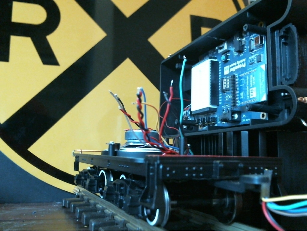
Here are some images of my current progress, I will be posting a schematic very soon, (working on it now) because its very hard to code by just staring at the wires to remember what goes where to what pin.
My web page control is not working due to a lack of SPIN examples with the Parallax WX wifi device, they have C examples which have helped me start the html code for the webpage control.
This will be slow going because I will need to learn how the C works and make an attempt to replicate it in spin. (feel free to get them examples made guys!)")
That is all for now, wish me luck.
When I first started to install the ActivityBoardWX into the tender, I quickly realized I had to remove the speaker.

https://forums.parallax.com/discussion/download/131231/Activity Board Tender.jpg
I got a bit farther in tender wiring here, this is when I did some WAVE sound tests, you can see my test spin CODE here (most of the code is from the obex, THANKS GUYS!!!!):
I currently use FlexGUI and SimpleIDE for coding and uploading the propeller programs via WIFI.
https://forums.parallax.com/discussion/comment/1504835/#Comment_1504835

https://forums.parallax.com/discussion/download/131509/TenderWire2.jpg
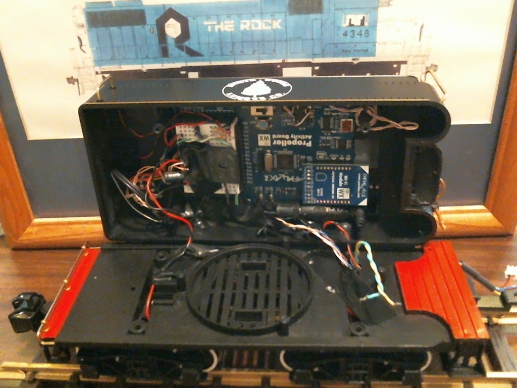
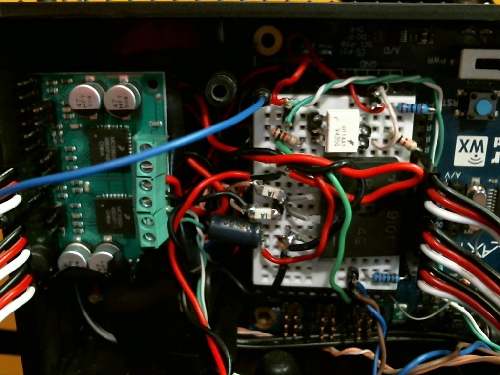
I have now wired EVERYTHING up, (except the 5v smoker, because I forgot to order the relay in the parallax store, darn shipping costs are more than the relay)
Heres an image of everything wired in the tender.

https://forums.parallax.com/discussion/download/131510/FullyWiredTender.jpg
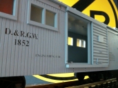
And here is an image with the tender and engine, up on test roller bearing's (bachmann g-scale brand)
I power the track with 14v DC from a PS2012 digitrax power supply set to N-scale voltage. (13.8v)
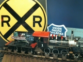
https://forums.parallax.com/discussion/download/131511/EngineWithTender.jpg
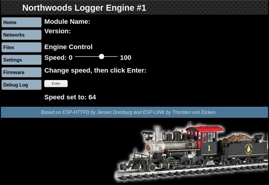
Here is the webpage control that I custom changed and compiled using my ESP compile instruction thread.
Link to esp compile thread: https://forums.parallax.com/discussion/169250/parallaxwx-esp8266-raspberrypi-debian-esp-open-sdk-simpleide-openspin-proploader-devel/
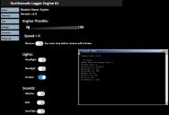
https://forums.parallax.com/discussion/download/131310/EngineControl.jpg
https://forums.parallax.com/discussion/download/131930/Smokin.jpg
My future plans are to wire up this engineering car with the track signals going to a LIPO battery powered Parallax Propscope connected via WIFI.
(esp8266 to esp8266 to prop plug to pc with propscope software, lol, no idea if that will work) to do TRACK diagnostics.
https://forums.parallax.com/discussion/download/131234/EngineeringCar.jpg
My bachmann caboose has a LGB rail cleaner kit (spring loaded) installed on the underside of the caboose.
I will NOT be manually cleaning the tracks. NO SIR!
I will be installing the bachmann smoker inside the caboose, once I fix the leaking issues, it will be powered by track power directly.(rectified and fused)
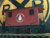
https://forums.parallax.com/discussion/download/131512/RailCleaner.jpg
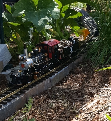
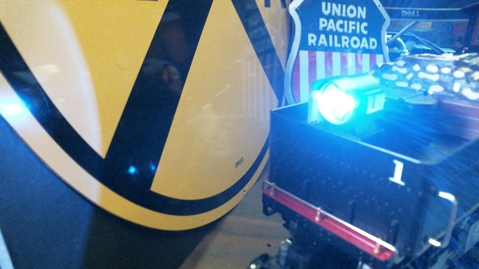
I installed a AMBER luxeon REBEL led in the front light.

https://forums.parallax.com/discussion/download/132000/AmberHeadlight.jpg
And a Luxeon Z Royal Blue led in the tender rear light.
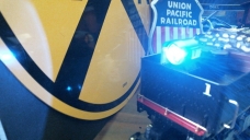
https://forums.parallax.com/discussion/download/132001/RoyalBlueTenderLight.jpg
V2.0 has better spin code and uses another wx module for dedicated webpage control.
Go to this link for 2.0 stuff.
https://forums.parallax.com/discussion/comment/1520649/#Comment_1520649
----OLDER VERSION 1.0
I absolutely love my new parallax powered train. (yoda: hmm, much have done you, far have gotten you. Train of light have you. mmmm)
Train of light: https://forums.parallax.com/discussion/comment/1507321/#Comment_1507321
I am in the process of building a Model Railroad Engine Controller.
This first post will have all the updated schematic, code, and images.
It will be edited to include the latest code and design as I develop them.
The latest code with html control is attached to this first post.
https://forums.parallax.com/discussion/download/132130/NorthwoodsLogger.zip
The caboose code is now included and I changed the way the motor is controlled at bit.
(I have removed the ground side diode, fuses, to prevent ground floating)
https://forums.parallax.com/discussion/download/132129/Northwoods Logger.pdf
Click link to get image bigger (3meg image)
https://forums.parallax.com/discussion/download/132128/Northwoods Logger.jpg
I purchased a North Woods Logger G-scale train set by Bachmann.
Everything about this train set sucks(mostly).
The track is cheap hollow steel, the engine smoke device leaks and is entirely too large, and barely puts out any smoke.
The leds are dim and a dull orangish color, the engine and tender circuitry is completely analog and useless.
The tender came with sound that literally sounds like someone banging a trashcan with a baseball bat,
(they used a hand full of discrete parts to make it), I'll give them an A+ for making a chuff sound with as little parts as possible.
The motor circuitry was almost nothing, it was powered by DC on the tracks.
I purchased a LGB 5v smoker, brass LGB track, bachmann is all about profit, made in china, and reduced costs as much as possible.
However their couplers are decent and look good, and cars look good, and engine frame/tender are ok, and all their wheels are metal, (surprisingly)
The tender has a large 1/2 watt 8ohm speaker which sounds ok with the proper amp and signal.
Currently the engine is only going to be controlled by a WIFI webpage that resides on a CODE customized Parallax WX Esp8266 WIFI device, connected to a ActivityBoardWX (rev1)
The track voltage is 14v and can be DCC because I am using a GBU4G full wave 4amp rectifier. (I need to include a larger capacitor than I currently use, so I just use 14vDC for now)
The motor drive is a Parallax Dual MC33926 board, which is fully wired for PWM control, status flag, and the current feedback is connected to the A2D chip on the ActivityBoardWX.
I currently only use 1 channel of the dual board, I will eventually use the other channel to power a cooling fan in the tender. (g-scale engines get hot in the outdoor sun)
The sound is also driven by the ActivityBoardWX, however I will need to find an amplifier, because it doesn't have enough power to push a 1/2 watt 8ohm speaker.
I pulled out the speakers from an old music cell phone, but they won't work due to a severe lack of power, with an amp of some kind, I can use the tender housing as a effective baffle.
Eventually I will drill small holes in the sides of the tender to use the cell phone speakers with, that is not my priority as I don't have an amp/circuit resolved yet.
The smoker was replaced with a LGB 5v smoker, which looks good quality, and doesn't look like it will leak, I will need to modify my setup to fit it in the smokestack, right now I just put it inside the smokestack sticking out.
The ActivityBoardWX is powered by 14v rectified track power (with the regular voltage drop from the rectifier).
I am currently using 1amp fuses during testing, but as I turn the motor, I will pop these, so I will need to use different fuses to power the motor board.
One of the axles inside the engine has a crude switch to sense the axle rotation for chuff sound, its just a copper metal flap pushing against the axle. The axle has 2 positions with conductive metal, so 1 full rotation of the axle will close the switch twice.
I wired the axle switch so that one side goes to ground, and the other goes to a H11AA1 optoisolators led, with a 1k resistor to 3.3v.
I will wire the optoisolator led to track voltage, because attaching it to 3.3v makes optoisolation pointless.
I just did this for testing, and the axle sensor SHOULDN'T ever touch track voltage, but bachmann made in china.. dont trust it.
I optoisolated the axle sensor for any possible shorts with track voltage of 14v, I don't want that going to my propeller pin.
The output of the H11AA1 goes to a prop pin with proper pull up resistor and a protection resistor going to the prop.
The headlight in the engine and the rear light in the tender will both be replaced with a Luxon Rebel LED with proper resistors to limit current, these are very bright at very low current, exactly what I want.
The rear light will be blue, and the headlight will be a white-orangeish color.
I would put a deep red rebel led into the firebox, and a white one in the cab, but I have run out of wires from the tender to the engine, I may just run another since its pretty easy, the wire bundle is already there.
I may one day use "EL wire" to make the engine look like the back to the future one, lol, but elwire uses seriously high voltage, so if I do that, it will be battery powered.
I would also only do that if I had other, better engines, like the big boy, and some diesel engines. (If wishes were fishes, we'd all live in the sea?)
The tender is the only electrical pickups for it all, which are copper metal pressed up against the metal on the axles, because I don't have enough wires to run electrical pickups from the loco also, but if it gets bad, i will wire those up also.
I am hoping a very large capacitor in the tender will solve that. I could replace the tender wheels with higher quality LGB ball bearing wheels that have nice electrical pickups with good connection points, but only if I need that.
The control of the engine is currently done using the Parallax WX esp8266 wifi device, and their open source code for it, I have modified it a bit so it looks more custom to the engine.
I don't have the code working at all for it yet, I am still learning how that happens, but the SPIN examples have left me in the dust, they are basically non-existant. The C code examples are excellent, and very thorough.
I am slowly learning how the C-code works and perhaps I can recreate it in spin, I am not sure how extensive it will be to make a spin file for the INCLUDE files they show in the c code to talk to the propeller.
The motor control in software is also something I will need to learn how to do, but that seems much easier than getting the WX to talk to spin code on the propeller.
I will also need to learn how to read the signal from the current feedback into the ActivityBoardWX A2D chip, I do not know if any examples exist in spin yet, I need to look into that.
I did some sound tests to play wave files from the microsd card plugged into the ActivityBoardWX. My tests went ok, but I quickly learned I will need to learn more to do multiple wave file output, if I want any kind of decent sound.
The idle, chuff, whistle, steam effects, brake squeel, coal shovel sound, wheel slip, and STACK TALK (very important), will all need to be able to be played simultaneously, so that means over 8+ wave files need to be accessed on the sd card and played independently, at any given time, potentially all of them at the same time. I don't know if the propeller is up to that task, I may need to limit that.
I plan to include more fuses and TVS diodes for an enhanced circuit protection, I am tired of my model railroad electronics frying.
This whole project was inspired by my problems with a brand name DCC command station going nuclear, up in smoke in less than 2 seconds simply because the manufacturer failed to include some of the most basic protection circuitry available.
for 10cents they could have saved a 250$ command station, a 60$ decoder/motor drive, and a 40$ sound unit. Seriously?
I gave up on the repair because after repairing 6 npn, and pnp transistors, the programming voltage still was not rising to the proper level, showing other damage that wasn't obvious.
You can read all about it here: https://forums.parallax.com/discussion/172039/can-ya-help-me-not-throw-250-into-the-trash-circuit-repair-help-request/
As far as DCC track control, I have not worked on this part, I may someday, but that would require more circuitry and extensive work in the SPIN program once I have all the above working I may start at.
But that would require me to create a Custom Command station of my own, this involves precise current sensors, powerful h-bridge, 10amp 14v power supply for it, and all the code involved, plus making a throttle device etc.
One problem with using wifi is I don't have a way to detect which block the train is in, for automation of train using JMRI control software.
However I have looked into multiple potential solutions to this and RFID might work, if I can get a RFID detector close enough to the tags that would be under the track.
I do not know if the track brass that has 14v dc would affect the RFID signal, I will need to do more testing to find out, and I have read some attempts by others to boost the range of RFID...
Using opto sensors for track block detection might work if the (IR) sensor is on the tender looking down at a reflective material of some sort, and even possibly using neodymium magnets under the track with reed switches on the tender trucks.
I would need to make each signal be unique so I can tell what part of the track I am on, that makes using IR and magnets abit more difficult, multiple (8 of them) sensors under the tender, on the trucks in strategic locations might work.
Then each sensor can be used in combination with others to make a unique "signal".
I just realized after reading this thread over, using a BARCODE laser scanner to read track zone barcodes in between the sleepers, might be a very realistic solution to this!!!!
THANKS BRAIN!
Here are some images of my current progress, I will be posting a schematic very soon, (working on it now) because its very hard to code by just staring at the wires to remember what goes where to what pin.
My web page control is not working due to a lack of SPIN examples with the Parallax WX wifi device, they have C examples which have helped me start the html code for the webpage control.
This will be slow going because I will need to learn how the C works and make an attempt to replicate it in spin. (feel free to get them examples made guys!)
That is all for now, wish me luck.
When I first started to install the ActivityBoardWX into the tender, I quickly realized I had to remove the speaker.
https://forums.parallax.com/discussion/download/131231/Activity Board Tender.jpg
I got a bit farther in tender wiring here, this is when I did some WAVE sound tests, you can see my test spin CODE here (most of the code is from the obex, THANKS GUYS!!!!):
I currently use FlexGUI and SimpleIDE for coding and uploading the propeller programs via WIFI.
https://forums.parallax.com/discussion/comment/1504835/#Comment_1504835
https://forums.parallax.com/discussion/download/131509/TenderWire2.jpg
I have now wired EVERYTHING up, (except the 5v smoker, because I forgot to order the relay in the parallax store, darn shipping costs are more than the relay)
Heres an image of everything wired in the tender.
https://forums.parallax.com/discussion/download/131510/FullyWiredTender.jpg
And here is an image with the tender and engine, up on test roller bearing's (bachmann g-scale brand)
I power the track with 14v DC from a PS2012 digitrax power supply set to N-scale voltage. (13.8v)
https://forums.parallax.com/discussion/download/131511/EngineWithTender.jpg
Here is the webpage control that I custom changed and compiled using my ESP compile instruction thread.
Link to esp compile thread: https://forums.parallax.com/discussion/169250/parallaxwx-esp8266-raspberrypi-debian-esp-open-sdk-simpleide-openspin-proploader-devel/
https://forums.parallax.com/discussion/download/131310/EngineControl.jpg
https://forums.parallax.com/discussion/download/131930/Smokin.jpg
My future plans are to wire up this engineering car with the track signals going to a LIPO battery powered Parallax Propscope connected via WIFI.
(esp8266 to esp8266 to prop plug to pc with propscope software, lol, no idea if that will work) to do TRACK diagnostics.
https://forums.parallax.com/discussion/download/131234/EngineeringCar.jpg
My bachmann caboose has a LGB rail cleaner kit (spring loaded) installed on the underside of the caboose.
I will NOT be manually cleaning the tracks. NO SIR!
I will be installing the bachmann smoker inside the caboose, once I fix the leaking issues, it will be powered by track power directly.(rectified and fused)
https://forums.parallax.com/discussion/download/131512/RailCleaner.jpg
I installed a AMBER luxeon REBEL led in the front light.
https://forums.parallax.com/discussion/download/132000/AmberHeadlight.jpg
And a Luxeon Z Royal Blue led in the tender rear light.
https://forums.parallax.com/discussion/download/132001/RoyalBlueTenderLight.jpg
1024 x 768 - 220K
1024 x 768 - 199K

1024 x 768 - 201K
1328 x 747 - 2M
422 x 460 - 123K
6336 x 4896 - 3M

Comments
https://forums.parallax.com/discussion/98150/multichannel-wav-player
If this is *really* the best way to do it, and if no one else has done a multichannel wav mixer using a single pin,
I will need to skip the ActivityBoardWX's audio output circuit and recreate the DAC circuit for up to 6 channels.
I guess I will stop looking for more multichannel spin stuff because this is the best I have found so far.
If anyone has other suggestions, let me know.
Time to move onto motor control, and reading the A2D.
A simple audio circuit for 19.4KHz rolloff uses R1=820R and C1= 10nF and 1uF-10uF. f3db=1/(2*pi*r1*c1)
Wouldn't be able to fit a P1 inside a N scale locomotive, but would be great for decoding CVs for lights and switches and such.
Up to 10 wav files @44100Hz could be combined by my calculations and mixed with the one output. Once cog would be busy reading and mixing the buffers, updating the output, timing and stepping to the next samples, while the other cog would be reading the wave files using sequential sectors. Only a single sector buffer is needed at a time and the two 512 byte wav buffers.
Do you mean instead of the circuit components posted above? (so the same circuit.)
I think SIDcog is a effects generator and will not playback wave files. I *could* try to find the perfect combination of all the various settings, similar to my black box,
Trying to coax the sounds like a bell, steam chuff, brake squeel, etc, is probably possible but I would be investing quite a bit of time tweaking the knobs.
I already did that game.. its fun but time consuming to find things..
https://forums.parallax.com/discussion/115258/theblackbox-release-v2-0-propeller-hss-fx-sequencer-with-digital-audio-spdif
I would rather hack up a video with all the wanted sounds, i've already done this with TANE: TRAINZ (the game), and it works pretty well, sounds great!
This clip has some nice chuffs to cut. I will need to find a video who's author permits me to do this and post the clips. (many good people exist who allow it, just gotta ask)
What DCC system did you go with?
Oh man, I feel for you, I have quite a bit of n-scale track, engine, cars... and digitrax dcc equiptment and I am abandoning it all, I just can't do nscale anymore, its too small to work with, when it comes to modifications and repairs etc...
I moved to g-scale...
When I do get more work done, I will probably come up with a circuit that can be heavily reduced in size.
But I doubt it can be reduced so much that it will fit in any nscale engine, but like you say could be used for a misc decoder
(if i ever get around to programming the decoder to talk DCC, deal with all the NMRA dcc rules and the specific circuitry to read the track along with allowing CV programming with programming track feedback)
Lots involved with DCC programming, right now I am just trying to get a wireless control going..
I will make a good effort to do it though, because I really want to see if I can achieve putting a prop in a nscale engine... somehow...
I actually already did this with a SX chip back in the day, and it fit in a boxcar, still too big (but I didn't use smt parts back then)
But like I said, n-scale man.. thats hardcore. I wouldn't recommend anyone go smaller than HO-scale, the repairs are too hard to do.
I have no idea how to do those things in tachyon, I would need to even learn how to blink a led in tachyon, lol.... ♫♪♯♫♪♯ ive got a long way to go... ♫♫♪♯♪♯and a short time to get there.....♫♪♯
I would prefer to stick to spin, which means I will probably just use 6 prop pins for the audio, (which I have plenty available even after all the above stuff. (if I don't limit myself to using a activity board and do a custom pcb. (which I will do)
They should be good for testing, and the motor drive can technically handle peaks of 5amp so perhaps they are perfect.
The fuses are installed before the full wave rectifier where the rail wires come in.
I also have 1amp smt fast blow fuses after the full wave rectifier which provide 14v to the activity board wx.
I have also included a 25v 2200uF cap after the rectifier to deal with DCC signal zero crossing dead time, i could use SUPERCAPS if I need to reduce the size to fit inside smaller engines.
But supercaps have a limited life, and usually need to be stacked to get to proper voltage.
Schematic still in process. Motor movements will be done today, and chuff sync to axle sensor. (I can do single channel wave sounds right now, I did a test, works great.)
I do enjoy soldering DIP pins to everything, makes prototyping easier.
I would have included the wav files but they are technically not mine to share, I ripped them from the generic steam engine file at https://www.digitrax.com/sound-depot/list/
I own 12 of their sdxn136ps decoders so I am sure I paid for them 10x over. (at least I can use them)
And used SPJHelper to rip out all the sounds. http://fnbcreations.net/spjhelper/index.html
That was to just quickly get some sounds, I will be ripping much better and higher quality sounds from a good steam engine video that the author approves me to post the clips.
I tried to get kyes player to do multiple wave output, but the sd card reader routine would need heavy modification.
I used Kye's wave player for a Mouse Droid project (for someone else). I recall the samples didn't sound very good unless they were saved at a specific bitrate. I'll try to find my project files and see if the bitrate is mentioned. I think I used the free audio program Audacity to change the bitrate.
https://forums.parallax.com/discussion/118866/parallax-bs2-control-of-an-ho-scale-rotary-dumper-and-train-positioner
And Another done on the prop
https://forums.parallax.com/discussion/111985/model-railroad-dcc-projects/p2
It looks like samples recorded at 1411kpbs didn't work as well as samples recorded at 1024bps.
If I remember correctly, changing the bitrate greatly improved the sound quality.
http://forums.parallax.com/discussion/171949/tinysdda-v1-0-sdcard-sector-r-w-stereo-music-sound-effects-in-one-cog-and-almost-no-hub-ram#latest
It totally DISABLES the ability to keep the gif data intact so the gif files play.
Great another thing that can't be used to help convey information, seriously who the hell tested this forum software before approving it.
Sorry, but that is so basic, its rediculous, it literally breaks gif's? Im surprised we can even type anything, and have it post....
DAMNIT.
Hey good to know, I will try that.!
Now thats what I am talking about! I will give it a try, I didn't see where it says that it can do MULTIPLE sounds simultaneously, but I haven't loaded the code yet, thanks.
I like n-scale because I can have an elaborate track layout without it taking up my whole house!
I hear that, I have entirely too much n-scale track now. Perhaps I can make a diorama. (LOL)
I sure hope you have better luck than I did with brand name digitrax stuff, their Smile dies very fast, the command station and their decoders, and their transponding / programming is bugged completely.
(transponding gets confused with what loco is where, and their programmer messes up, if your transponder is turned on)
One good thing to me wasting my money on it, was I now know extensive details about DCC, transponding, programming, command stations, and decoders, due to my attempt to analyze the track signals and circuitry.
https://forums.parallax.com/discussion/167921/reading-dcc-data-using-a-propeller-on-track-digital-model-railway-control/p1
This gif only works because it was uploaded before this forum software decided to start trashing uploaded gifs.
Here is the exact same GIF file uploaded just now.
It doesn't work anymore. SUPER LAME
Obviously it's a simple test, when I get more layout going with switches and such, then I'll know more.
https://www.parallax.com/product/28440
Along with the tag: RFID R/W 54 x 85 mm Rectangle Tag
https://www.parallax.com/product/28441
I placed the TAG under the sleepers of a G-scale UNPOWERED track and the TAG is read every time I attempt it...
This is good news. Because I placed the reader on the TOPSIDE of a flatbed g-scale railroad log car, which makes it at least 2 inches away, my plans are to place the reader much closer, (under the car's bottom frame.
So RFID might just be a viable option for doing zoning.
I need to test more by connecting it to a rail car with a long wire to the serial, and do a rolling drive past the tag to see if it is still read properly. I also need to try powering the track with 14v DC and see if that messes it up.
But the brass track seems to not mess up the signal of that specific tag, I tried other tags (RFID R/W 30 mm Round Tag) (12.4 mm Round RFID Tag) and they didn't work.
Use with PUTTY it has ANSI command codes.
{{
┌───────────────────────────────────────────┐
│ RFID RFID Read/Write Object Wrapper       │
│ Author: TinkersALot                       │
│ Adapted from Joe Grand's BS2 code.        │
│ See end of file for terms of use.         │
└───────────────────────────────────────────┘
Modified by Clock Loop to do only reading of the read write tags.
Also modifed to do a fast loop of the read with one attempt per read.
The driver was also modified to do no pause in the RFID.Reader.Writer.Driver.
So this will repeatedly hammer your read/writer to do a read of a read/write tag.

}}

CON

  _clkmode      = xtal1 + pll16x                        ' use crystal x 16
  _xinfreq      = 5_000_000

  RFID_TX              = 23    ' Connects to RFID R/W Module SIN
  RFID_RX              = 22   ' Connects to RFID R/W Module SOUT

  Tx             = 30   'serial out to wx device
  Rx             = 31   'serial in from wx device


obj

  Host  : "FullDuplexSerial"
  RFID  : "RFID.Reader.Writer.Driver"

var

  byte TestBuffer[ 12 ]

PUB Start
{{
  Test this driver
}}
  ' start the host interface ( connected to PST )
  '
  ErrCheck := Host.Start(Rx, Tx, 0, 115_200)

  waitcnt(80_000_000 + cnt)

  Host.str(string(27))    'Set command mode
  Host.str(string("[2J"))    'Clear telnet screen


  Host.str(string(27))    'Set command mode
  Host.str(string("[1;3f"))  'Set Position

  if 0 == ErrCheck
    Host.str( string( "Cog Start Error", 13 ) )


  else
    Host.str(string("RFID Reader/Writer Started."))
    ' since host interface started, the next thing to do is to
    ' call the driver start method to start its I/O interface
    '
    ErrCheck := RFID.Start( RFID_RX, RFID_TX )
    if 0 == ErrCheck
      Host.str( string( "Cog Start Error", 13 ) )


  ' if everything worked above, then enter terminal I/O loop
  '
  if ErrCheck <> 0

    Host.str( string( "Ready.") )
    Host.str(string(27))    'Set command mode
    Host.str(string("[2;3f"))  'Set Position
    Host.str( string( "Reading tag's unique serial number...", 13 ) )

    RfidLoop

PUB RfidLoop | LoopCounter
  repeat

        Result := RFID.TryGetCardSerialNumber( @TestBuffer, 1 )
        if Result <> 0
          Host.str(string(27))    'Set command mode
          Host.str(string("[3;3f"))  'Set Position
          repeat LoopCounter from 0 to 4
            Host.hex( TestBuffer[ LoopCounter ], 2 )

        else
          Host.str(string(27))    'Set command mode
          Host.str(string("[3;3f"))  'Set Position
          Host.str( string( "            ") )

DAT

CmdByte   byte    0
ErrCheck  byte    0

{{
┌──────────────────────────────────────────────────────────────────────────────────────────────────────────────────────────────┐
│                                                   TERMS OF USE: MIT License                                                  │
├──────────────────────────────────────────────────────────────────────────────────────────────────────────────────────────────┤
│Permission is hereby granted, free of charge, to any person obtaining a copy of this software and associated documentation    │
│files (the "Software"), to deal in the Software without restriction, including without limitation the rights to use, copy,    │
│modify, merge, publish, distribute, sublicense, and/or sell copies of the Software, and to permit persons to whom the Software│
│is furnished to do so, subject to the following conditions:                                                                   │
│                                                                                                                              │
│The above copyright notice and this permission notice shall be included in all copies or substantial portions of the Software.│
│                                                                                                                              │
│THE SOFTWARE IS PROVIDED "AS IS", WITHOUT WARRANTY OF ANY KIND, EXPRESS OR IMPLIED, INCLUDING BUT NOT LIMITED TO THE          │
│WARRANTIES OF MERCHANTABILITY, FITNESS FOR A PARTICULAR PURPOSE AND NONINFRINGEMENT. IN NO EVENT SHALL THE AUTHORS OR         │
│COPYRIGHT HOLDERS BE LIABLE FOR ANY CLAIM, DAMAGES OR OTHER LIABILITY, WHETHER IN AN ACTION OF CONTRACT, TORT OR OTHERWISE,   │
│ARISING FROM, OUT OF OR IN CONNECTION WITH THE SOFTWARE OR THE USE OR OTHER DEALINGS IN THE SOFTWARE.                         │
└──────────────────────────────────────────────────────────────────────────────────────────────────────────────────────────────┘
}}
I did a basic rolling test past 2 different RFID R/W 54 x 85 mm Rectangle Tag's and I am COMPLETELY SATISFIED with the results.
Actually I am impressed with the results showing the proper serial number at very fast cycle speeds, and its ON TOP of the flatbed railcar.
My plans are to mount the reader on the underside of the engine tender, that will make it at least 1/2 inch closer.
This was also with the motor unloaded up on the roller bearings, as in one of the pictures above, so no load. Load tests come later.
I LIKE IT!
Now I will combine my chuff test with the motor movement to have the axle sensor trigger the chuff wave files.
Time to get the A2D on the Activity board Wx, going, and display that info on the terminal while making motor movement.
Then comes pwm movements with the A2D.
{{ dc_motor_03.spin May 30, 2012 Greg Denson Spin code modified by Clock Loop to only test 1 motor on the M1 pins. }} CON _CLKMODE=XTAL1 + PLL16X ' The system clock spec _XINFREQ = 5_000_000 ' Crystal Tx = 30 'serial out to wx device Rx = 31 'serial in from wx device INV = 4 '(VDD - OVERRIDE), (Not used in this basic demo) SLEW = 5 '(VDD - OVERRIDE), (Not used in this basic demo) EN = 6 '(VDD - OVERRIDE), (Enable - connect to VDD to enable carrier) DO NOT EVER CONNECT TO MOTOR VIN M1SF = 7 '(Status Flag - not used in this basic demo) M1D1 = 8 '(PWM), (GND - OVERRIDE) (Motor 1, Disable 1) M1D2 = 9 '(PWM), (VDD - OVERRIDE) (Motor 1, Disable 2) M1IN1 = 10 '(Motor 1, Input 1) M1IN2 = 11 '(Motor 1, Input 2) VDD = 12 ' VDD (motor board pin 3) Only used for pullup resistors, safe to control with prop. DO NOT EVER CONNECT TO MOTOR VIN M1fbDI = 18 '(Feedback of current draw - not used in this basic demo) M1fbDO = 19 '(Feedback of current draw - not used in this basic demo) M1fbSCL = 20 '(Feedback of current draw - not used in this basic demo) M1fbCS = 21 '(Feedback of current draw - not used in this basic demo) PUB Go dira[M1IN1]~~ ' Main Cog - Set direction to output (Controls for Motor 1) dira[M1IN2]~~ ' Main Cog - Set direction to output (Controls for Motor 1) dira[M1D1]~~ ' Main Cog - Set direction to output (Controls for Motor 1) dira[M1D2]~~ ' Main Cog - Set direction to output (Controls for Motor 1) dira[EN]~~ ' Main Cog - Set direction to output (Enable Carrier Board) dira[VDD]~~ ' Main Cog - Set direction to output (Enable Carrier Board) outa[VDD]~~ ' Set Pin VDD to high to enable PULL up resistors. repeat outa[M1IN1] := 0 ' Set Pin (M1IN1) to low outa[M1IN2] := 1 ' Set Pin (M1IN2) to high - Reversing the setings on Pins M1IN1 & M1IN2 will reverse motor direction outa[M1D1] := 0 ' Set Pin (M1D1) to low turns off the Disable setting for Motor 1 outa[M1D2] := 1 ' Set Pin (M1D2) to high (100% or full speed) - Setting Pin M1D2 to low will stop motor outa[EN] := 1 ' Set Pin (EN)to high to enable carrier board 'NOTE: Above settings turn motor in Forward directon. Switching the settings on Pins M1IN1 & M1IN2 will reverse ' the direction of Motor 1. ' Changing setting of Pin EN will disable the entire board. Changing setings on Pins M1D1 can disable ' the individual motors.https://github.com/parallaxinc/propeller/tree/master/libraries/community/p1/All/MC33926 Demonstration
I think it would be WISE to change that to PLL16X
And I thought it was my optoisolator circuit and axle sensor..
And the OBEX has a DCC driver. Hmm
https://github.com/parallaxinc/propeller/tree/master/libraries/community/p1/All/DCC Driver
I found the board very confusing the first time I tried to use it. If you're finding the instructions confusing, I'd be glad to try to remember what I know about it. I used a dual MC33926 when I was updating the Eddie firmware to use with newer Arlo hardware. This post shows my robot using the MC33926.
In off chance you want to try a different PWM driver, I've posted an example of one in the second post of this thread.
Thanks for letting us follow along on your project.
Its all working great, but my axle switch is bouncing all over the place.
(see image with propscope triggered BOING!)
The chuff is all outta wak, and i need to record multiple wave files for different speeds (the p1 isn't up to stretching pcm, live, heh, tahts a P2 job. )
lol I might need to switch it to a ir sensor.
GUYS, this is SO much fun. (really)
Terminal used is PUTTY.
{{ Audio code by By: Kwabena W. Agyeman - 9/27/2013 Spin code by Clock Loop, made to only test 1 motor on the M1 pins, and the axle sensor to trigger the wav file chuff. }} CON _CLKMODE=XTAL1 + PLL16X ' The system clock spec _XINFREQ = 5_000_000 ' Crystal Rx = 31 'serial in from wx device Tx = 30 'serial out to wx device AxleSense = 3 ' High means sensor not active. Sensor goes low twice per revolution of the axle. INV = 4 ' A logical high value inverts the meaning of IN1 and IN2 for both motor drivers SLEW = 5 ' Output slew rate selection input. A logical LOW results in a slow output rise time (1.5 μs – 6 μs). ' A logical HIGH selects a fast output rise time (0.2 μs – 1.45 μs). ' This pin should be set HIGH for high-frequency (over 10 kHz) PWM. This pin determines the slew rate mode for both motor driver ICs. EN = 6 ' Enable input: when EN is LOW, both motor ICs are in a low-current sleep mode. M1SF = 7 ' Status flag output: an over-current (short circuit) or over-temperature event will cause SF to be latched LOW. ' If either of the disable pins (D1 or D2) are disabling the outputs, SF will also be LOW. ' Otherwise, this pin is weakly pulled high. ' This allows the two SF pins on the board to be tied together and connected to a single MCU input. M1D1 = 8 ' Disable input: when D1 is high, OUT1 and OUT2 are set to high impedance. ' A D1 PWM duty cycle of 70% gives a motor duty cycle of 30%. ' Typically, only one of the two disable pins is used, but the default is for both disable pins to be active. M1D2 = 9 ' Disable input: when D1 is high, OUT1 and OUT2 are set to high impedance. ' A D1 PWM duty cycle of 70% gives a motor duty cycle of 30%. ' Typically, only one of the two disable pins is used, but the default is for both disable pins to be active M1IN1 = 10 ' The logic input control of OUT1. PWM can be applied to this pin (typically done with both disable pins inactive) M1IN2 = 11 ' The logic input control of OUT2. PWM can be applied to this pin (typically done with both disable lines inactive) VDD = 12 ' VDD Only used for pullup resistors, safe to control with prop, NEVER connect this to VIN. M1fbDI = 18 '(Feedback of current draw - not used in this basic demo) M1fbDO = 19 '(Feedback of current draw - not used in this basic demo) M1fbSCL = 20 '(Feedback of current draw - not used in this basic demo) M1fbCS = 21 '(Feedback of current draw - not used in this basic demo) lPin = 26 'left audio output rPin = 27 'right audio output doPin = 22 'sd card DO pin clkPin = 23 'sd card CLK pin diPin = 24 'sd card DI pin csPin = 25 'sd card CS pin wpPin = -1 'Needed for sound code - unused cdPin = -1 'Needed for sound code - unused max_duty = 75 'My motor goes too fast higher. These drastically change when using slew 1 min_duty = 35 'My motor dosen't turn lower. These drastically change when using slew 1 MotorFreq = 1000 'Lower than 10k is a more quiet motor. These drastically change when using slew 1 OBJ ser: "FullDuplexSerial.spin" wav1: "V2-WAV_DACEngine.spin" pwm1 : "pwmasm" pwm2 : "pwmasm" VAR long spinPlayer1Stack[100] long spinPlayer2Stack[100] long parameter PUB main ser.Start(RX, TX, 0, 115200) waitcnt(80_000_000 + cnt) 'Wait for 1 s ser.str(string(27)) 'Set command mode ANSI command for putty terminal program. ser.str(string("[2J")) 'Clear telnet screen. ser.str(string(27)) 'Set command mode ser.str(string("[1;1f")) 'Set Position if(wav1.begin(lPin, rPin, doPin, clkPin, diPin, csPin, wpPin, cdPin)) ser.Str(string("Start: Success", 10, 13)) else ser.Str(string("Start: Failure", 10, 13)) wav1.setLeftVolume(3) wav1.setRightVolume(3) cognew(Chuff, @spinPlayer1Stack) ' Startup separate process. Repeat 5 'Let sound system start. waitcnt(80_000_000 + cnt) 'Wait for 1 s cognew(AxleRotation, @spinPlayer2Stack) ' Axle sensor. MotorFwdFull 'Start motor drive. Pub AxleRotation | a 'Axle sensor routine. ChuffCount := 0 dira[AxleSense]~ 'Set axle sensor direction to input Repeat waitcnt(20_000_000 + cnt) 'Wait for 1/4 s If INA[AxleSense] == 1 a := 0 If INA[AxleSense] == 0 AND a == 0 ChuffCount++ a := 1 If ChuffCount > 8 ChuffCount := 0 PUB Chuff repeat If ChuffCount == 2 ser.str(string(27)) 'Set command mode ser.str(string("[3;3f")) 'Set Position ser.Str(string("/ Chuff ")) ser.str(string(27)) 'Set command mode ser.str(string("[1;1f")) 'Set Position result := \wav1.play(string("chuff1.wav")) ChuffCount++ If ChuffCount == 4 ser.str(string(27)) 'Set command mode ser.str(string("[3;3f")) 'Set Position ser.Str(string("- Chuff")) ser.str(string(27)) 'Set command mode ser.str(string("[1;1f")) 'Set Position result := \wav1.play(string("chuff2.wav")) ChuffCount++ If ChuffCount == 6 ser.str(string(27)) 'Set command mode ser.str(string("[3;3f")) 'Set Position ser.Str(string("\ Chuff ")) ser.str(string(27)) 'Set command mode ser.str(string("[1;1f")) 'Set Position result := \wav1.play(string("chuff3.wav")) ChuffCount++ If ChuffCount == 8 ser.str(string(27)) 'Set command mode ser.str(string("[3;3f")) 'Set Position ser.Str(string("| Chuff")) ser.str(string(27)) 'Set command mode ser.str(string("[1;1f")) 'Set Position result := \wav1.play(string("chuff4.wav")) ChuffCount++ If(wav1.playErrorNum) ser.Str(string("WAV Error: ")) ser.Str(result) ser.Tx(10) ser.Tx(13) repeat PUB MotorFwdFull | x dira[M1IN1]~~ ' Set direction to output (Controls for Motor 1) dira[M1IN2]~~ ' Set direction to output (Controls for Motor 1) dira[M1D1]~~ ' Set direction to output (Controls for Motor 1) dira[M1D2]~~ ' Set direction to output (Controls for Motor 1) dira[SLEW]~~ ' Set direction to output (Slew Controls for Motor 1 and 2) dira[EN]~~ ' Set direction to output (Enable Carrier Board) dira[VDD]~~ ' Set direction to output (Enable Carrier Board) outa[VDD] := 1 ' Set Pin VDD to high to enable PULL up resistors, NEVER connect this to VIN. ' outa[Slew] := 0 ' Set Pin SLEW Output slew rate selection input. A logical LOW results in a slow output rise time ' (1.5 μs – 6 μs). A logical HIGH selects a fast output rise time (0.2 μs – 1.45 μs). ' This pin should be set HIGH for high-frequency (over 10 kHz) PWM. This pin determines the slew rate mode for both motor driver ICs. ' Setting this to a 1 with a duty of 1000 also works. outa[M1IN1] := 0 ' The logic input control of OUT2. PWM can be applied to this pin (typically done with both disable lines inactive) Reversing the setings on Pins M1IN1 & M1IN2 will reverse motor direction outa[M1IN2] := 1 ' The logic input control of OUT1. PWM can be applied to this pin (typically done with both disable pins inactive) Reversing the setings on Pins M1IN1 & M1IN2 will reverse motor direction outa[M1D1] := 0 ' Disable input: when D1 is high, OUT1 and OUT2 are set to high impedance. ' A D1 PWM duty cycle of 70% gives a motor duty cycle of 30%. ' Typically, only one of the two disable pins is used, but the default is for both disable pins to be active. 'outa[M1D2] := 1 ' Disable input: when D1 is high, OUT1 and OUT2 are set to high impedance. 'A D1 PWM duty cycle of 70% gives a motor duty cycle of 30%. 'Typically, only one of the two disable pins is used, but the default is for both disable pins to be active outa[EN] := 1 ' Set Pin (EN)to high to enable carrier board 'pwm1.start(M1D1) pwm2.start(M1D2) pwm2.SetPeriod(MotorFreq) repeat repeat x from min_duty to max_duty 'linearly advance parameter from 0 to 100 'pwm1.SetDuty(x) pwm2.SetDuty(x) repeat 5 waitcnt(80_000_000 + cnt) 'wait 1 second before next update DAT ChuffCount byte 0 {{ /////////////////////////////////////////////////////////////////////////////////////////////////////////////////////////////// // TERMS OF USE: MIT License /////////////////////////////////////////////////////////////////////////////////////////////////////////////////////////////// // Permission is hereby granted, free of charge, to any person obtaining a copy of this software and associated documentation // files (the "Software"), to deal in the Software without restriction, including without limitation the rights to use, copy, // modify, merge, publish, distribute, sublicense, and/or sell copies of the Software, and to permit persons to whom the // Software is furnished to do so, subject to the following conditions: // // The above copyright notice and this permission notice shall be included in all copies or substantial portions of the // Software. // // THE SOFTWARE IS PROVIDED "AS IS", WITHOUT WARRANTY OF ANY KIND, EXPRESS OR IMPLIED, INCLUDING BUT NOT LIMITED TO THE // WARRANTIES OF MERCHANTABILITY, FITNESS FOR A PARTICULAR PURPOSE AND NONINFRINGEMENT. IN NO EVENT SHALL THE AUTHORS OR // COPYRIGHT HOLDERS BE LIABLE FOR ANY CLAIM, DAMAGES OR OTHER LIABILITY, WHETHER IN AN ACTION OF CONTRACT, TORT OR OTHERWISE, // ARISING FROM, OUT OF OR IN CONNECTION WITH THE SOFTWARE OR THE USE OR OTHER DEALINGS IN THE SOFTWARE. /////////////////////////////////////////////////////////////////////////////////////////////////////////////////////////////// }}Those wheels are spinning SO FAST. And it only pulls 400ma at 11.2v Im sure that will change once its under load from cars and incline...
I need to get that A2D working... for the Feedback. Looking at Jon "JonnyMac" McPhalen's code now.
Casey Jones was setup, it was sabotage. Jealous engineers.
Oh, I just purchased the bachmann stuff to get a kit, I knew it would be not as good as others.
I am not too picky between 1/32 scale or 1/29 or what not, and I will run both on the 45mm track, that is if I can even ever afford an engine that isn't 400$+
(the local hobby shop that sells tons of used stuff who will be getting my business a lot!)
They had a nice quality box car that I purchased for 45$.
I will just take their used, non digital engines and convert them using this threads developments that I achieve.
Its VERY likely I will be making a custom propeller board with all the parts included (or at least a way to plug the motor drive board into the main pcb,... I haven't decided yet....
Time to work on the A2D current feedback signal from the motor drive.
I am also working the code to detect the rise to HIGH and then fall to LOW, non bounce signal that shows on the prop scope, from the axle switch.
I measured a period of 90ms at full speed where the signal is high the entire time, with no bouncing of the switch.
So I will do a WAITPEQ during that time, and measure the result of time that passes, and if too little passes, I will do a loop to measure again, only accepting a minimum of 90ms as the signal for the axle switch.
At minimum speed I measured a maximum high time of 258ms.
I think detecting a minimum HIGH time of 90ms should do the trick, it may not be perfect, but I think it will be better than triggering on every low-high-low transition like my code did earlier.
I still need to find a simple example of sending data from the WX webpage TO the spin code and then from the spin code to the WX, the only examples I have found so far are done in C.
I need the example to show the spin side, I do not quite get how to do that yet. And I only need 1 example, i can take it from there.
If ANYONE has an example of this PLEASE POST IT HERE!!
Once I get the WX spin code going I will post a copy.
Ok, after searching the 32420-Parallax-Wi-Fi-Module-API-v1.0, it says this:
3. Via a Break Condition on the Serial interface itself
          a. Set the DI pin low for ≥ 30/baud rate,    seconds.
This works to generate a break to the WX module.
Thats why the spin WX code wasn't working.
  dira[WXDI]~~          ' Set pin to output
  outa[WXDI]     := 0   'Send UART break to WX di pin.

  waitcnt(80_000_000 + cnt)    'wait one second.

  FDS.start(WXDO,WXDI,0,115200)   ' Prop rxpin, Prop txpin, mode,baudrate
DEBUG output from WX debug pin.
YAAAY!
*moves notch one up. only 1 million more to go...
I am going to play the freely available game: https://www.openttd.org/
You also can git it and compile it yourself. https://github.com/OpenTTD/OpenTTD
Put the Folder inside another folder (because of the way it builds, on linux)
Then run cmake with the folder name.
Then it will make the make files.
Then you can run make, the game icon will be in your games folder.
It looks like the original design had the different wav files output on different pins to allow for the panning fly-by, so you might be able to have a single output pin just by adjusting the wavplayer.spin file. I'd think the bigger issue is that you need one Cog per wav file, meaning that you'll need more than one Propeller to play 8+ simultaneously, or you'd need to have some sounds that are mutually exclusive in time and adjust the code for multiple wav files per Cog.
Peter's suggestion seems to be the better avenue to pursue, consuming only two Cogs, and having the output on a single pin. You'd need Tachyon, but if you asked nicely I think you'd find someone could show you how to integrate it with a SPIN program.
Wouldn't typical train sounds be somewhat like that? Wouldn't a train tend to have a continuous chug-chug sound, with whistle or brake sounds only sounding occasionally, and maybe only when triggered? Except in your case I'd guess there would be adding of the sounds.
Funny story - many years ago I had a great WAV recording of a train driveby; it started with an approaching horn blast on the left channel, got louder and louder as it approached, raced past to the right channel, played the clacking of train wheels for about a minute, then faded to silence.
Anyway, I'd just gotten a new ipod and had put some of my favorite songs on it. I went for a walk down the sidewalk of a fairly busy street during lunchtime at work, listening to music.
All of a sudden, there's this tremendous blast of a train whistle to my left. I spun around and jumped to the back of the sidewalk trying to get out of the way, but it followed me, getting louder and louder, and I was jerking my head left and right looking for the danger, until finally I realized that the ipod software had found that WAV file in my computer and had automatically added it to my music collection without telling me!
Anyway, I still enjoy hacking around with propeller-driven sd WAV players, so I'll be interested in what you come up with, and maybe help a little, if you'd like.
David
The very basic method would stop any sound and play the new one, and even that (stopping mid play) is hard for players to do (i could just stop the cog)...
But to make it sound really good, simultaneous sounds are really nice. I have multiple sound decoders that do 3 or 4 simultaneous sounds at once, the chug keeps going, or the idle sound while you play the bell or the whistle.
You can have the chug, the bell AND the whistle all play at once.
Trains that are near stations with passengers ring the bell, and usually only do it when they are about to move and are moving, which means a chug or engine sound.
And if there is a rr crossing directly ahead of them, they will do all 3 sounds at once.
And it would be kinda odd to hear a chug sound stop just to play a whistle or a brake squeel.
I would have LOVED to see you do this from a 3rd party perspective, must have been hilarious.
Oh, darn I thought your player did simultaneous output, did't you write the sd driver to access multiple files data inter-weaved?
That is what i would REALLY need, because If I must I can run multiple COGS to play two waves on two pins that are tied externally.
I thought yours played up to 6 like that, I didn't actually test it yet.
To accomplish this the quality of the sound file can be greatly reduced to like mono, 16khz, 16bit...
But I am not good with propasm, and am only OK with spin, so I could NOT accomplish this kind of thing by myself, I stand on the backs of giants like yourself!
I would be very grateful for any help to accomplish my goal of simultaneous wave output.
I have no idea whats involved when it comes to accessing SD cards for wav data, and then the details of cranking it out to a pin.
You might be right about tachyon, I haven't even started to look into it due to my attention being on coding in spin to talk to the Parallax WX esp wifi module,
From a spin program on the prop to a webpage on the WX, and back again on the module, so i can get the engine moving around the track via wireless.
I have the motor code working great, I just need the control.
The last part will be the sound and the motor control current feedback.
I think this project would be a GREAT first project to try to convert to P2, but all the spin code examples are currently in P1 so that might need to wait for all you CODE GIANTS to move into the p2.
For now I am just doing as much as I can with the P1, and its already looking VERY good.
Anyone who wants to help with code examples, that would be AWESOME!
This entire project will be open source, and when I get it moving on the track wirelessly, I WILL be posting the entire schematic along with the program.
EVERYONE is free to hack it up, and store it in their basement freezer.
Would make things over complicated.
Tachyon and Spin both want to be the master with their memory map.
If you want to have Tachyon it will be a rewrite.
With quite a learning curve.
But so rewarding
Because so many building blocks are there already.
And all is made to work smoothly together.