Be absolutely certain the four bridge diodes (BD601) are working. You don't want one of those to be a short with a new bus capacitor.
I'm not sure why but it looks like there is two paths from the main bridge to the bus capacitor. It looks like a diode each end of the PFC inductor/transformer. Both D651 and D652 (? Can't quite read it). With D652 being the PFC rectifier (D1 in the reference schematic).
Best guess for powering the ICs is via the SCR, IC603. Too complicated for me but I suspect it's a low voltage supply from the main transformer, T601 (? Not visible). It looks to be additionally feed by resistors R604 and R605. These should be the startup resistors. I can't make out the colour codes on them, 47k ohms I presume? Test them.
@evanh said:
Be absolutely certain the four bridge diodes (BD601) are working. You don't want one of those to be a short with a new bus capacitor.
I'm not sure why but it looks like there is two paths from the main bridge to the bus capacitor. It looks like a diode each end of the PFC inductor/transformer. Both D651 and D652 (? Can't quite read it). With D652 being the PFC rectifier (D1 in the reference schematic).
Best guess for powering the ICs is via the SCR, IC603. Too complicated for me but I suspect it's a low voltage supply from the main transformer, T601 (? Not visible). It looks to be additionally feed by resistors R604 and R605. These should be the startup resistors. I can't make out the colour codes on them, 47k ohms I presume? Test them.
Yeah, already tested the bridge rectifier chip and found diodes between all four pins as expected. The schematic is more complicated than the reference designs. I found this link which shows something for what might be used in the 2407 version which is very similar. There is some minor difference to the 2405FPW but this is the main core of the supply apparently.
I retested all diodes and apart from the gate drive output diode that is in parallel with a low value 47ohm resistor they all gave their usual drop. All FETs still have their Source Drain body diode observed in one direction (so not shorted) and bipolar transistors seemed okay with two diodes observed from B-E and B-C. Didn't know how to probe the unpowered SCR for a sanity test.
I found there is another workaround and that is to use a laptop brick power supply to feed 19-20V into the monitor's DC speaker output jack (with some minor wiring tweaks to bridge it to the main 19V DC bus), and remove the fuse so no AC power plugs can have any effect. It's a bit ugly and probably wasteful of power but people are reporting good results with that solution, so if I can't get this first one going or the second one which exploded I may resort to that, to at least keep one of these things working. But I'll have a quick go at the cap first.
EDIT: looks like Zener ZD601 supplies both active chips, and one of the optocouplers is used to disable the PFC circuit in standby to save power via Q654.
Oh, R603 is the startup resistor for regulator IC according to those rough schematics. So the IC is not directly on the DC bus at all. The colours look like maybe brown-black-orange? 10 kohm.
Check all resistors dropping from the +DC bus rail. From the schematic, that's R603, R604, R605, R607, R609 and optionally R657, R658, R660, R661. And R601 and thermistor TR601 for good measure. TR601, if it is there, will be low resistance and will look like a matt black disc.
Check R615 as well. If it's been cooked it may be open circuit. Power supply will be write-off material if open circuit.
@rogloh said:
EDIT: looks like Zener ZD601 supplies both active chips, and one of the optocouplers is used to disable the PFC circuit in standby to save power via Q654.
Yep. It's supplied from D603/C606 which in turn is charged from an isolated winding of the main transformer. But none of that is operating until the regulator IC is doing it's job. To get that going, R603 supplies the IC.
Oh man, opened the second dead monitor (which had exploded) and removed its power supply. This one copped a beating!
So far I found it blew the a_s_s out of the PFC controller IC651 as well as open circuited its 0.22ohm R670 current sense resistor. The main 450V filter cap has leaked badly, and it probably fully corroded the terminal by now so it has likely gone open circuit which triggered this. Quite a bit worse than the first power supply cap I removed before.
PFC switching MOSFET Q651 has died (internally shorted on all 3 terminals), and the primary fuse is blown too. Zener ZD601 is also shorted out now. Given this took out my entire house circuit breaker at the time of all this happening I'm not surprised.
There's probably other damage too if I probe other resistors. Remaining diodes and transistors seemed okay but I wouldn't trust the main PWM switcher chip, best for me to try to replace that one as well. Hopefully out of the two monitors I might still get one going, and I'd be satisfied with that.
Yeah, most everything will be fried. Takes a lot to wipe out the current sense resistor. What about the other 0.22 ohm resistor, R615? I'd guess the original problem was simply a surge that took the bus volts over 450 Volts, which means your 230 V AC supply went beyond 320 VAC. The capacitor leakage could be a result.
Have you checked those resistors I listed for the prior power supply?
@evanh said:
Yeah, most everything will be fried. Takes a lot to wipe out the current sense resistor. What about the other 0.22 ohm resistor, R615?
That one was still okay on both.
I'd guess the original problem was simply a surge that took the bus volts over 450 Volts, which means your 230 V AC supply went beyond 320 VAC. The capacitor leakage could be a result.
Could be the case. The initial surge/outage seemed to be the trigger for the cascade of failures following it. Although I did read that these caps are also prone to leak over time according to other failures mentioned by people on badcaps.net site. Will have to check/replace surge protector gear I am using. I believe my powerstrip had one inside, but maybe it has failed over time - will have to figure out what monitor plugged into what outlet etc and it's a ratsnest back there of course. Probably 20 or more cords for all this stuff by now.
Have you checked those resistors I listed for the prior power supply?
In the process...I did see another SMD resistor on supply #2 that was toast - R669 which would have fed the high voltage into the PFC controller chip. Hole present in the chip resistor, possibly also on a cap C620 which has a mark that could be a hole can't be 100% sure unless desoldered I guess.
This supply #2 is not good. I may get some replacement components for it to try but doubt it will be fully successful unless I replace lots of parts and identify all the bad ones, unfortunately don't have the SMD cap values if they need replacing. So it may need a separate 19.5V supply, assuming the LCD panel itself didn't fry. Supply #1 might work again with any luck.
@evanh said:
Please check the resistances I listed for supply #1.
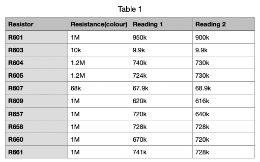
I checked these and found no open circuits but found the 1M ohm ones were all reading around 640-720k ohms when in theory they should have been 1M. This was double checked on two different meters as well with essentially the same result. I also checked power supply #2 to be sure and they basically read the same values. I also tested in both probe directions and the results are attached for #1. I believe I'd need to desolder them to test accurately. In circuit they must be finding a reverse/parallel path under test making it impossible to be 100% sure of the values. Thermistor TR601 was still intact and read a few ohms.
That's all good, thanks. R603 was the one I was most concerned about. The higher the resistances are the harder they'll be to get a decent reading while in circuit.
Cool, the parts should be ordered tomorrow from Digikey with any luck and I can then attempt a fix on both, doing #1 first. The original 60kHz PWM switcher is obsolete now, but I can get a 40kHz variant as a replacement for supply #2 assuming that chip is dead as well.
Here's the list of damaged parts to be ordered so far - I have the other blown 1k SMD resistor here and can source other through hole stuff locally if required.
2, 493-6893-ND, Nichicon Electrolytic 120uF 450V capacitors in radial can @AUD$8.15ea ex gst
1, 497-4582-1-ND, PFC corrector IC @AUD$2.40
1, 497-5892-5-ND, MOSFET @AUD$5.37
1, A137268CT-ND, 0.22ohm resistor 2W 5% @AUD$0.73
2, TZM5245B-GS08CT-ND, 15V 0.5W Zeners Mini-MELF @AUD$0.35ea
2, 486-0001.1010.TRCT-ND, 4A HBC ceramic fuses @AUD$2.36ea
1, NCP1200D40R2GOSCT-ND, PWM controller IC for flyback converter @AUD$1.82
Be great if this will get something going again for under $40 in parts...
Gotta say, GUIs are Smile at using EDID. And monitors are Smile with EDID support too. There's no range flexibility at all. They could do ranges but they don't. It's all a mess.
Bring on VRR at the desktop level! Fingers crossed they don't screw that up too.
EDIT: Actually, I need to go try a VRR monitor before I spout off too much about limits of everything else (There was legitimate timing limits with traditional LCD, and I don't really know how those were overcome. Presume it was a case of where there is a will there is a way) ...
EDIT2: Right, been to the shops and tested Windoze MediaPlayer on a 100 Hz monitor using a selection of different framerate (40,45,50,55,60,65,70 Hz) videos in full-screen mode. Only the one at 50 Hz ran consistently smooth ... So, the media player, at least, doesn't make use of VRR. Sadly, it's probably a Direct3D only feature at this stage.
I sort of wonder is there any detrimental effect of VRR on people's vision. I know I used to get motion sickness bad after like 20mins with FPS games if the system lagged in various places with fixed rate monitors, so I wonder if it still has a similar effect with VRR or not, or if it creates any other issues if the frame rate varies while you play. I've stopped gaming since then so don't know how good/bad VRR really is and I still don't have a VRR monitor at this time. I always felt fast frame rate games if you had a decent enough graphics card to keep up and displayed on high performance VGA monitors (no LCDs) running at like 75Hz+ etc, didn't give me the same motion sickness (or at least reduced it). As soon as I transitioned to LCDs the experience degraded with tearing and blur etc, all the bad things and I stopped gaming around then too. But LCDs were pretty slow back in the mid 2000s and have undoubtedly massively improved since then.
It can't get worse. The PC has always been the worst case scenario.
As for LCDs, I think blurring is still an issue generally. I haven't studied the new ones extensively either.
I'm actually okay with tearing in 3D games. I prefer that over visual stutters.
OLED with VRR would be the one to really test out.
Okay, here's a small clip of three framerates I tested with. Took me a while to find a tool that would simply adjust a video's specified framerate without all the transcoding hoops.
PS: The middle of the clip has one dropped frame - presumably when it was recorded. So it always has that one stutter.
@evanh said:
EDIT2: Right, been to the shops and tested Windoze MediaPlayer on a 100 Hz monitor using a selection of different framerate (40,45,50,55,60,65,70 Hz) videos in full-screen mode. Only the one at 50 Hz ran consistently smooth ... So, the media player, at least, doesn't make use of VRR. Sadly, it's probably a Direct3D only feature at this stage.
I think VRR only works on full-screen V-synced applications and only when it's specifically enabled and I think the monitor must be connected using native DisplayPort? There's nothing special about VRR from the LCD side, it still ends up having a minimum scan rate where it works correctly. I think some of the timing/voltage parameters need to be adjusted on-the-fly.
@evanh said:
It can't get worse. The PC has always been the worst case scenario.
The year is 2024 and you still can't do smooth animation on PCs without getting interrupted by random background junk (or your own process starving the compositor process...). And the past few years there's been a lot of games using that fundamentally broken system where there's thousands of redundant shader programs and they get compiled on-demand when the relevant material enters the viewport. Not sure what they do these days, but in the olden days they never had full multitasking systems on dedicated game consoles. On 3DS, they just give up one of the two CPU cores to the main application and the other core is interrupted at a fixed rate to switch between OS services and application threads. So there's always a fixed amount of cycles. (And of course the GPU is controlled directly by the application)
@Wuerfel_21 said:
I think VRR only works on full-screen V-synced applications and only when it's specifically enabled
I was using full screen and quite definitely v-sync'd. No tearing and had a distinctive framerate stepping effect going on. I can believe VRR will require enabled, and I'm thinking it's only exposed through DirectX.
and I think the monitor must be connected using native DisplayPort?
Yeah, something like that. I think even laptops have some sort of miniDP system now as well. The days of raw LCD interface at the GPU seem gone. Maybe for the better.
There's nothing special about VRR from the LCD side, it still ends up having a minimum scan rate where it works correctly.
There's no real minimum at the GPU end when the monitor's scan converter can refresh the last frame as a still image indefinitely. nVidia have always stipulated 1 Hz.
I think some of the timing/voltage parameters need to be adjusted on-the-fly.
Quite likely given that drive biasing was tuned to the refresh in the past. The LCD panel has to handle the range from max rate down to half that. The scan converter handles everything lower with frame repeats.
@evanh said:
I'm hopeful for #1. Not so much for #2. ZD601 is deeply embedded, there's going to be other collateral damage around that, more than just IC601.
Got parts yesterday.
Worked on Dell 2405FPW monitor supply #1 this morning by soldering in a new 120uF Nichicon main filter cap to replace the leaking one. Plugged into 240V power and covered my eyes as I reluctantly flipped the main switch waiting for an immediate explosion. No bang and the power supply output the expected DC voltages when I tested the rails. Happy days. Refit inside monitor and got it working right away on the DVI input (still to test other inputs but I think they'll be fine too).
Can work on supply #2 at my leisure now I have one of these monitors going again. I now have all the parts I found were bad but this one may not be fixable if I didn't locate all the bad parts and could potentially fry itself again on first powerup. Plus I don't like the fact I have a 40kHz PWM switcher IC to use instead of the original 60kHz device (obsolete) as I don't imagine it would be able to generate the same power output and the inductor current might be affected or more heating could occur. So long as I don't crank to full brightness which requires most of the power it might still work out but I'm not holding my breath. Ultimately I might have to do the 19.5V DC conversion to fix my second monitor, which is okay. I expect the panel itself is still probably okay but don't know for sure. I could use supply #1 to prove that but for now it's back inside its monitor again and it is a bi-atch to reopen.
Fitted replacement parts into supply #2 from second Dell 2405FPW monitor today. This one had taken all the damage and I wasn't sure it would be repairable, but through some fault finding, an analysis of the schematic & data sheets, and a bit of luck with probing components, I was able to get it working again. Not a bad result for under $40 or so considering I was about to take it to the e-waste rubbish dump.
Here were the parts I replaced (minus another MELF diode and SMD resistor which got lost on the floor!)
Installed back into monitor.
Working again! Still to test other analog inputs using my P2 driver but I imagine it will be fine.
DAMN! That's six florescence tubes there for the backlight. I never expected that.
The very first LCD display of any sort I ever purchased used LED backlighting. I stayed using CRTs and one Plasma TV until then. Oops, I do have to admit to buying a shitty laptop for work with my own money at one stage. That was a mistake on both counts.
@evanh said:
Well done. Way more motivated than me!
With a schematic (or one close enough to this model) it mades it simpler to figure out the problem. It's a good monitor and has useful inputs for video driver development and testing. I was looking at what it would take to achieve these inputs on another HDMI monitor and it could get costly or would create yet another ratsnest of multiple converters to deal with. For example I'd love to have one of these things to mate up with my input box but they're pricey... https://www.startech.com/en-au/audio-video-products/vs721multi
DAMN! That's six florescence tubes there for the backlight. I never expected that.
Yeah and after all these years of use they're still going okay. I was looking into possible LED backlight conversions but from what seems its not worth it to do for these and it risks breaking the thing getting it fully open.
@evanh you might be in luck with a solution to your longstanding bugbear. As part of the current driver restructuring work I'm doing I am also looking into reorganising my video driver's timing structure which may help align to nicer boundaries and not use as many small bitfields. I still don't want to use a single long for every individual parameter but I think I can work with word boundaries where it makes sense.
Here's the structure I am considering, right now it's at 9 longs vs 7 longs currently so it only added 2 longs more which isn't too bad. Main gain now is that the key video timing fields are easier to setup because upper level P2 setup code can readily read/write words in HUB RAM already. With 16 bits per field we have enough bits to setup any streamer command even up to its full size. No need to go higher.
long CLKMODE ' desired operating clock mode
long P2FREQ  ' desired operating P2 clock frequency
long xfreq  ' SETXFRQ value or optionally a (fractional) divider
long cfreq  ' custom CFRQ setting for PAL/NTSC modulator output

word flags 'vsync polarity, hsync polarity, (maybe some use in the future for selecting interlaced sync, or for refresh rate override selection)
word breezeway<<8 | colorburst ' only needed for PAL/NTSC modes

word horizontal_fp_pixels
word horizontal_sync_pixels
word horizontal_bp_pixels
word columns  ' = 8*active_pixels

word vertical_fp_lines
word vertical_sync_lines
word vertical_bp_lines
word visible_lines
Here's the existing
long   CLK252MHz ' Optional stored P2 PLL+clock settings required for
                 ' this mode.  The high level code controlling the
                 ' driver can make use of this information when
                 ' spawning the driver COG to change PLL settings
                 ' when new resolutions are selected etc.

long   252000000 ' CPU clock frequency value when PLL setting is applied

      '_HSyncPolarity___FrontPorch__SyncWidth___BackPorch__Columns
      '     1 bit        7 bits      8 bits      8 bits    8 bits
long   (SYNC_POS<<31) | ( 16<<24) | ( 96<<16) | ( 48<<8 ) | (640/8)

      '_VSyncPolarity___FrontPorch__SyncWidth___BackPorch__Visible
      '     1 bit        8 bits      3 bits      9 bits   11 bits
long   (SYNC_NEG<<31) | ( 37<<23) | (  2<<20) | ( 60<<11) | 350

long   10<<8 ' This behaves either as the P2 clock divider word or
             ' as a custom XFRQ value.  If the most significant word
             ' is zero the lower word is used as 16 bit divider,
             ' otherwise the entire 32 bits becomes the XFRQ value.
             ' The 16 bit divider is comprised of an integer portion
             ' in the upper byte, and fractional portion in the LSB.

      '_Breezeway__C-Burst__FrontPorchHi__SyncWidthHi__BackPorchHi
      '  8 bits     8 bits     8 bits        4 bits        4 bits
long    0    ' Optional timing extension/mode dependent parameters.
             ' Bits 15:0 extend the horizontal timing range further.
             ' This increased range enables support for wider front
             ' porches used in 720p50 modes etc.
             '     bits 3:0 become bits 11-8 of horizontal back porch
             '     bits 7:4 become bits 11-8 of horizontal sync width
             '     bits 15:8 become bits 14-7 of horizontal front porch
             '  Additionally, for PAL/NTSC composite/S-video output:
             '     bits 23:16 hold colour burst size (pixels)
             '     bits 31:24 hold colour burst breezeway size (pixels)

long    0    ' Custom CFRQ setting for PAL/NTSC modulator output.
Also I've located my earlier parallel RGB/LCD driver work I did on another system some time ago (thankfully I didn't lose it in the migration to my new Mac) and am importing that into the basic driver to be re-tested. This allows driving of LVTTL/LVCMOS RGB video in arbitrary bus sizes up to 24 bits as well as CLK/DE/VSYNC/HSYNC and optional simultaneous RGB DAC outputs from the driver. In theory it could allow CGA/EGA too (LOL).
@rogloh said:
@evanh you might be in luck with a solution to your longstanding bugbear. As part of the current driver restructuring work I'm doing I am also looking into reorganising my video driver's timing structure which may help align to nicer boundaries and not use as many small bitfields. I still don't want to use a single long for every individual parameter but I think I can work with word boundaries where it makes sense.
For something that I thought would be straightforward, this change has caused no end of problems in the code with some subtle dependencies on the timing structure. I think I've finally fixed them all now but it's been a bit of a struggle with various unanticipated things breaking along the way.


Comments
Be absolutely certain the four bridge diodes (BD601) are working. You don't want one of those to be a short with a new bus capacitor.
I'm not sure why but it looks like there is two paths from the main bridge to the bus capacitor. It looks like a diode each end of the PFC inductor/transformer. Both D651 and D652 (? Can't quite read it). With D652 being the PFC rectifier (D1 in the reference schematic).
Best guess for powering the ICs is via the SCR, IC603. Too complicated for me but I suspect it's a low voltage supply from the main transformer, T601 (? Not visible). It looks to be additionally feed by resistors R604 and R605. These should be the startup resistors. I can't make out the colour codes on them, 47k ohms I presume? Test them.
Yeah, already tested the bridge rectifier chip and found diodes between all four pins as expected. The schematic is more complicated than the reference designs. I found this link which shows something for what might be used in the 2407 version which is very similar. There is some minor difference to the 2405FPW but this is the main core of the supply apparently.
https://www.badcaps.net/filedata/fetch?id=1923841
and
https://www.badcaps.net/filedata/fetch?id=1929028 from
https://www.badcaps.net/forum/troubleshooting-hardware-devices-and-electronics-theory/troubleshooting-computer-displays/25344-dell-2405fpw-power-supply-fault?t=27183&highlight=2407WFPb+schematic
I retested all diodes and apart from the gate drive output diode that is in parallel with a low value 47ohm resistor they all gave their usual drop. All FETs still have their Source Drain body diode observed in one direction (so not shorted) and bipolar transistors seemed okay with two diodes observed from B-E and B-C. Didn't know how to probe the unpowered SCR for a sanity test.
I found there is another workaround and that is to use a laptop brick power supply to feed 19-20V into the monitor's DC speaker output jack (with some minor wiring tweaks to bridge it to the main 19V DC bus), and remove the fuse so no AC power plugs can have any effect. It's a bit ugly and probably wasteful of power but people are reporting good results with that solution, so if I can't get this first one going or the second one which exploded I may resort to that, to at least keep one of these things working. But I'll have a quick go at the cap first.
EDIT: looks like Zener ZD601 supplies both active chips, and one of the optocouplers is used to disable the PFC circuit in standby to save power via Q654.
Oh, R603 is the startup resistor for regulator IC according to those rough schematics. So the IC is not directly on the DC bus at all. The colours look like maybe brown-black-orange? 10 kohm.
Check all resistors dropping from the +DC bus rail. From the schematic, that's R603, R604, R605, R607, R609 and optionally R657, R658, R660, R661. And R601 and thermistor TR601 for good measure. TR601, if it is there, will be low resistance and will look like a matt black disc.
Check R615 as well. If it's been cooked it may be open circuit. Power supply will be write-off material if open circuit.
Yep. It's supplied from D603/C606 which in turn is charged from an isolated winding of the main transformer. But none of that is operating until the regulator IC is doing it's job. To get that going, R603 supplies the IC.
Oh man, opened the second dead monitor (which had exploded) and removed its power supply. This one copped a beating!
So far I found it blew the a_s_s out of the PFC controller IC651 as well as open circuited its 0.22ohm R670 current sense resistor. The main 450V filter cap has leaked badly, and it probably fully corroded the terminal by now so it has likely gone open circuit which triggered this. Quite a bit worse than the first power supply cap I removed before.
PFC switching MOSFET Q651 has died (internally shorted on all 3 terminals), and the primary fuse is blown too. Zener ZD601 is also shorted out now. Given this took out my entire house circuit breaker at the time of all this happening I'm not surprised.
There's probably other damage too if I probe other resistors. Remaining diodes and transistors seemed okay but I wouldn't trust the main PWM switcher chip, best for me to try to replace that one as well. Hopefully out of the two monitors I might still get one going, and I'd be satisfied with that.
Yikes, quite an event
Yeah, most everything will be fried. Takes a lot to wipe out the current sense resistor. What about the other 0.22 ohm resistor, R615? I'd guess the original problem was simply a surge that took the bus volts over 450 Volts, which means your 230 V AC supply went beyond 320 VAC. The capacitor leakage could be a result.
Have you checked those resistors I listed for the prior power supply?
That one was still okay on both.
Could be the case. The initial surge/outage seemed to be the trigger for the cascade of failures following it. Although I did read that these caps are also prone to leak over time according to other failures mentioned by people on badcaps.net site. Will have to check/replace surge protector gear I am using. I believe my powerstrip had one inside, but maybe it has failed over time - will have to figure out what monitor plugged into what outlet etc and it's a ratsnest back there of course. Probably 20 or more cords for all this stuff by now.
In the process...I did see another SMD resistor on supply #2 that was toast - R669 which would have fed the high voltage into the PFC controller chip. Hole present in the chip resistor, possibly also on a cap C620 which has a mark that could be a hole can't be 100% sure unless desoldered I guess.
This supply #2 is not good. I may get some replacement components for it to try but doubt it will be fully successful unless I replace lots of parts and identify all the bad ones, unfortunately don't have the SMD cap values if they need replacing. So it may need a separate 19.5V supply, assuming the LCD panel itself didn't fry. Supply #1 might work again with any luck.
Please check the resistances I listed for supply #1.
I checked these and found no open circuits but found the 1M ohm ones were all reading around 640-720k ohms when in theory they should have been 1M. This was double checked on two different meters as well with essentially the same result. I also checked power supply #2 to be sure and they basically read the same values. I also tested in both probe directions and the results are attached for #1. I believe I'd need to desolder them to test accurately. In circuit they must be finding a reverse/parallel path under test making it impossible to be 100% sure of the values. Thermistor TR601 was still intact and read a few ohms.
That's all good, thanks. R603 was the one I was most concerned about. The higher the resistances are the harder they'll be to get a decent reading while in circuit.
Cool, the parts should be ordered tomorrow from Digikey with any luck and I can then attempt a fix on both, doing #1 first. The original 60kHz PWM switcher is obsolete now, but I can get a 40kHz variant as a replacement for supply #2 assuming that chip is dead as well.
Here's the list of damaged parts to be ordered so far - I have the other blown 1k SMD resistor here and can source other through hole stuff locally if required.
2, 493-6893-ND, Nichicon Electrolytic 120uF 450V capacitors in radial can @AUD$8.15ea ex gst
1, 497-4582-1-ND, PFC corrector IC @AUD$2.40
1, 497-5892-5-ND, MOSFET @AUD$5.37
1, A137268CT-ND, 0.22ohm resistor 2W 5% @AUD$0.73
2, TZM5245B-GS08CT-ND, 15V 0.5W Zeners Mini-MELF @AUD$0.35ea
2, 486-0001.1010.TRCT-ND, 4A HBC ceramic fuses @AUD$2.36ea
1, NCP1200D40R2GOSCT-ND, PWM controller IC for flyback converter @AUD$1.82
Be great if this will get something going again for under $40 in parts...
I'm hopeful for #1. Not so much for #2. ZD601 is deeply embedded, there's going to be other collateral damage around that, more than just IC601.
Gotta say, GUIs are Smile at using EDID. And monitors are Smile with EDID support too. There's no range flexibility at all. They could do ranges but they don't. It's all a mess.
Bring on VRR at the desktop level! Fingers crossed they don't screw that up too.
EDIT: Actually, I need to go try a VRR monitor before I spout off too much about limits of everything else (There was legitimate timing limits with traditional LCD, and I don't really know how those were overcome. Presume it was a case of where there is a will there is a way) ...
EDIT2: Right, been to the shops and tested Windoze MediaPlayer on a 100 Hz monitor using a selection of different framerate (40,45,50,55,60,65,70 Hz) videos in full-screen mode. Only the one at 50 Hz ran consistently smooth ... So, the media player, at least, doesn't make use of VRR. Sadly, it's probably a Direct3D only feature at this stage.
I sort of wonder is there any detrimental effect of VRR on people's vision. I know I used to get motion sickness bad after like 20mins with FPS games if the system lagged in various places with fixed rate monitors, so I wonder if it still has a similar effect with VRR or not, or if it creates any other issues if the frame rate varies while you play. I've stopped gaming since then so don't know how good/bad VRR really is and I still don't have a VRR monitor at this time. I always felt fast frame rate games if you had a decent enough graphics card to keep up and displayed on high performance VGA monitors (no LCDs) running at like 75Hz+ etc, didn't give me the same motion sickness (or at least reduced it). As soon as I transitioned to LCDs the experience degraded with tearing and blur etc, all the bad things and I stopped gaming around then too. But LCDs were pretty slow back in the mid 2000s and have undoubtedly massively improved since then.
It can't get worse. The PC has always been the worst case scenario.
As for LCDs, I think blurring is still an issue generally. I haven't studied the new ones extensively either.
I'm actually okay with tearing in 3D games. I prefer that over visual stutters.
OLED with VRR would be the one to really test out.
Oh, attachment file size limit of only 2 MB now!
Okay, here's a small clip of three framerates I tested with. Took me a while to find a tool that would simply adjust a video's specified framerate without all the transcoding hoops.
PS: The middle of the clip has one dropped frame - presumably when it was recorded. So it always has that one stutter.
I think VRR only works on full-screen V-synced applications and only when it's specifically enabled and I think the monitor must be connected using native DisplayPort? There's nothing special about VRR from the LCD side, it still ends up having a minimum scan rate where it works correctly. I think some of the timing/voltage parameters need to be adjusted on-the-fly.
The year is 2024 and you still can't do smooth animation on PCs without getting interrupted by random background junk (or your own process starving the compositor process...). And the past few years there's been a lot of games using that fundamentally broken system where there's thousands of redundant shader programs and they get compiled on-demand when the relevant material enters the viewport. Not sure what they do these days, but in the olden days they never had full multitasking systems on dedicated game consoles. On 3DS, they just give up one of the two CPU cores to the main application and the other core is interrupted at a fixed rate to switch between OS services and application threads. So there's always a fixed amount of cycles. (And of course the GPU is controlled directly by the application)
I was using full screen and quite definitely v-sync'd. No tearing and had a distinctive framerate stepping effect going on. I can believe VRR will require enabled, and I'm thinking it's only exposed through DirectX.
Yeah, something like that. I think even laptops have some sort of miniDP system now as well. The days of raw LCD interface at the GPU seem gone. Maybe for the better.
There's no real minimum at the GPU end when the monitor's scan converter can refresh the last frame as a still image indefinitely. nVidia have always stipulated 1 Hz.
Quite likely given that drive biasing was tuned to the refresh in the past. The LCD panel has to handle the range from max rate down to half that. The scan converter handles everything lower with frame repeats.
Got parts yesterday.
Worked on Dell 2405FPW monitor supply #1 this morning by soldering in a new 120uF Nichicon main filter cap to replace the leaking one. Plugged into 240V power and covered my eyes as I reluctantly flipped the main switch waiting for an immediate explosion. No bang and the power supply output the expected DC voltages when I tested the rails. Happy days. Refit inside monitor and got it working right away on the DVI input (still to test other inputs but I think they'll be fine too).
Can work on supply #2 at my leisure now I have one of these monitors going again. I now have all the parts I found were bad but this one may not be fixable if I didn't locate all the bad parts and could potentially fry itself again on first powerup. Plus I don't like the fact I have a 40kHz PWM switcher IC to use instead of the original 60kHz device (obsolete) as I don't imagine it would be able to generate the same power output and the inductor current might be affected or more heating could occur. So long as I don't crank to full brightness which requires most of the power it might still work out but I'm not holding my breath. Ultimately I might have to do the 19.5V DC conversion to fix my second monitor, which is okay. I expect the panel itself is still probably okay but don't know for sure. I could use supply #1 to prove that but for now it's back inside its monitor again and it is a bi-atch to reopen.
Nice. Good going.
I know nothing about transformer frequency characteristics. No idea how much impact 40 kHz will make, sorry.
Fitted replacement parts into supply #2 from second Dell 2405FPW monitor today. This one had taken all the damage and I wasn't sure it would be repairable, but through some fault finding, an analysis of the schematic & data sheets, and a bit of luck with probing components, I was able to get it working again. Not a bad result for under $40 or so considering I was about to take it to the e-waste rubbish dump.
Here were the parts I replaced (minus another MELF diode and SMD resistor which got lost on the floor!)
Installed back into monitor.
Working again! Still to test other analog inputs using my P2 driver but I imagine it will be fine.
Well done. Way more motivated than me!
DAMN! That's six florescence tubes there for the backlight. I never expected that.
The very first LCD display of any sort I ever purchased used LED backlighting. I stayed using CRTs and one Plasma TV until then. Oops, I do have to admit to buying a shitty laptop for work with my own money at one stage. That was a mistake on both counts.
With a schematic (or one close enough to this model) it mades it simpler to figure out the problem. It's a good monitor and has useful inputs for video driver development and testing. I was looking at what it would take to achieve these inputs on another HDMI monitor and it could get costly or would create yet another ratsnest of multiple converters to deal with. For example I'd love to have one of these things to mate up with my input box but they're pricey...
https://www.startech.com/en-au/audio-video-products/vs721multi
Yeah and after all these years of use they're still going okay. I was looking into possible LED backlight conversions but from what seems its not worth it to do for these and it risks breaking the thing getting it fully open.
Wow Roger! Isn't it great when those efforts (/gambles) work out
I'll let you know when the next repair cafe is : )
@evanh you might be in luck with a solution to your longstanding bugbear. As part of the current driver restructuring work I'm doing I am also looking into reorganising my video driver's timing structure which may help align to nicer boundaries and not use as many small bitfields. I still don't want to use a single long for every individual parameter but I think I can work with word boundaries where it makes sense.
Here's the structure I am considering, right now it's at 9 longs vs 7 longs currently so it only added 2 longs more which isn't too bad. Main gain now is that the key video timing fields are easier to setup because upper level P2 setup code can readily read/write words in HUB RAM already. With 16 bits per field we have enough bits to setup any streamer command even up to its full size. No need to go higher.
Here's the existing
long CLK252MHz ' Optional stored P2 PLL+clock settings required for ' this mode. The high level code controlling the ' driver can make use of this information when ' spawning the driver COG to change PLL settings ' when new resolutions are selected etc. long 252000000 ' CPU clock frequency value when PLL setting is applied '_HSyncPolarity___FrontPorch__SyncWidth___BackPorch__Columns ' 1 bit 7 bits 8 bits 8 bits 8 bits long (SYNC_POS<<31) | ( 16<<24) | ( 96<<16) | ( 48<<8 ) | (640/8) '_VSyncPolarity___FrontPorch__SyncWidth___BackPorch__Visible ' 1 bit 8 bits 3 bits 9 bits 11 bits long (SYNC_NEG<<31) | ( 37<<23) | ( 2<<20) | ( 60<<11) | 350 long 10<<8 ' This behaves either as the P2 clock divider word or ' as a custom XFRQ value. If the most significant word ' is zero the lower word is used as 16 bit divider, ' otherwise the entire 32 bits becomes the XFRQ value. ' The 16 bit divider is comprised of an integer portion ' in the upper byte, and fractional portion in the LSB. '_Breezeway__C-Burst__FrontPorchHi__SyncWidthHi__BackPorchHi ' 8 bits 8 bits 8 bits 4 bits 4 bits long 0 ' Optional timing extension/mode dependent parameters. ' Bits 15:0 extend the horizontal timing range further. ' This increased range enables support for wider front ' porches used in 720p50 modes etc. ' bits 3:0 become bits 11-8 of horizontal back porch ' bits 7:4 become bits 11-8 of horizontal sync width ' bits 15:8 become bits 14-7 of horizontal front porch ' Additionally, for PAL/NTSC composite/S-video output: ' bits 23:16 hold colour burst size (pixels) ' bits 31:24 hold colour burst breezeway size (pixels) long 0 ' Custom CFRQ setting for PAL/NTSC modulator output.Also I've located my earlier parallel RGB/LCD driver work I did on another system some time ago (thankfully I didn't lose it in the migration to my new Mac) and am importing that into the basic driver to be re-tested. This allows driving of LVTTL/LVCMOS RGB video in arbitrary bus sizes up to 24 bits as well as CLK/DE/VSYNC/HSYNC and optional simultaneous RGB DAC outputs from the driver. In theory it could allow CGA/EGA too (LOL).
If I can dig up that AHD CCTV stuff I did a while back I'll try to get that in too. That probably goes along with the colour space stuff I still hope to fix as well.
EDIT: Found the related thread. https://forums.parallax.com/discussion/comment/1552784/#Comment_1552784
For something that I thought would be straightforward, this change has caused no end of problems in the code with some subtle dependencies on the timing structure. I think I've finally fixed them all now but it's been a bit of a struggle with various unanticipated things breaking along the way.
Thanks Roger. Looks great. Will be much more readable as a mode description too.