What is the lowest vertical refresh for your monitor, can it do much less than 50Hz? That's where my monitors (both analogue and digital ones) seem to die, around 49Hz or so.
@rogloh said:
What is the lowest vertical refresh for your monitor, can it do much less than 50Hz? That's where my monitors (both analogue and digital ones) seem to die, around 49Hz or so.
Yes, 49 to 61 Hz. But both the TV and newer monitor are happy with 24 to 75 Hz. Basically, displays that are newer than something like 2013 are much more flexible.
I have 2 Philips monitors at the university, both from 2020. One 27" which doesn't complain and displays 40 Hz, the second one, 24" doesn't like anything less than 49 Hz.
At home I have a cheap Chinese 15" TV and AOC 32" monitor which i didn't test for low vsync yet, but the TV doesn't like any non-standard VGA modes, including 50 Hz, while it accepts 50 Hz on HDMI input.
@pik33 said:
I have 2 Philips monitors at the university, both from 2020. One 27" which doesn't complain and displays 40 Hz, the second one, 24" doesn't like anything less than 49 Hz.
At home I have a cheap Chinese 15" TV and AOC 32" monitor which i didn't test for low vsync yet, but the TV doesn't like any non-standard VGA modes, including 50 Hz, while it accepts 50 Hz on HDMI input.
I'm only talking about behaviour with digital links, namely DVI and HDMI. Analogue VGA inputs are another story altogether.
Cool, ticked that one off. I've converted all my EDID code over to C so then I could make familiar use of standard C file handling in FlexC using an SD card.
All went pretty smoothly. Would still like to add date stamping from a RTC but don't have the hardware on hand so have used a separate text file to specific the date instead.
I've tested it wandering around the house plugging into the remaining other displays. Discovered that pin9 of VGA connector, like pin18 of HDMI connector, can activate the EDID of attached display without any display power. Although, like everything about EDID, this don't always work.
PS: Gotta say that that edid-decode program is pretty cool the way it handles many encodings of the EDID data dump.
EDIT: Attached the source code. What I do is put the compiled binary, named as _BOOT_P2.BIX, on a uSD card and also create a DATE.TXT with a date string that then is added to each dump within the report file. Pop the uSD card into the uSD slot of the Eval Board and connect the HDMI or VGA accessory - needs the SCL/SDA wires added as per above. And finally I plug in a USB battery pack to the AUX power input.
Good effort. Could be handy to know a little more about a monitor this way by just connecting it directly to a P2 system, although that benefit is obviously going to be completely dependent on how accurate and comprehensive the vendors are when providing the monitor's EDID details.
The interest is partly to see how varied they are ... and partly to check out supposedly more modern monitors to see what the date of each EDID actually is. Looking at you, Pik, and that fussy Philips monitor!
If the C is compatible with flexC you could port that EDID decoding code I posted earlier onto to the P2 as well and have the monitor display its own EDID information on screen for a full standalone thing. LOL, it could even use its own decoded information to build a timing for displaying of resulting data on screen, or just default to bog standard 60Hz VGA which is most likely going to be supported by the majority of monitors I would expect. Some P2 pins could be used as up/down switches to scroll through the data on screen if it takes up more than one screen's worth.
It did cross my mind, and I've not actually checked, but I'm quite happy with how it is. It's doing a little more than just the decoding too, not to mention the mode timings getting listed aren't a lot of use. They're just the boring known ones. The hex dump I collect can still be further decoded with that edid-decode program of course.
One extra feature is the report includes a list of all responding device/bus addresses outside of EDID spec. This is a spill-over of example code of Jon's even. All bar one display, so far, has had multiple address ping responses. The old Dell DVI monitor is on its own in that respect. And that includes a couple of even older VGA-only monitors as well. I still have one working CRT, and an LCD from someone else's discarded fluorescent backlighting days.
The older Spin code I had, at one stage, also dumped blocks from those other device/bus addresses but the C code doesn't have that as yet.
Okay, a stumble later ... updated to also dump a block from each non-EDID ping.
EDIT: That's weird, I still had a bunch of Spin hexadecimals in the source code. I'm surprised they didn't cause compile errors ... okay, bug fixed those now.
EDIT2: And one @ address-of too. Also didn't cause a compile error or even a bug for that matter. It's almost like Eric has allowed both syntaxes in FlexC.
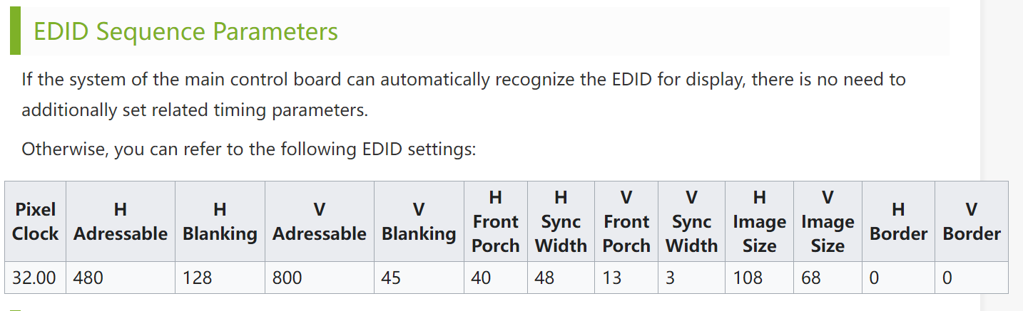
I'm trying to configure p2textdrv0.93 (which appear to hold the matching p2videodrv files) for a waveshare 4" HDMI 800x480.
It would appear that I'm to add/adjust the code block that looks like this:
updated with values found on the Waveshare wiki like this:
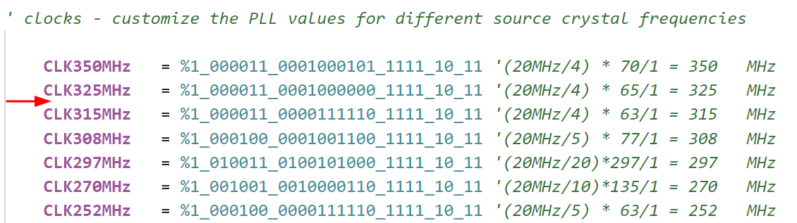
and then add a 320MHz ? PLL clock setting here:?
Am I on the right track?
I don't know how to match up all the numbers from the waveshare data into the timing blocks nor how the bits are derived for the PLL.
Alternately... the VGA mode does appear to come out clearly in the textdemo, except that the display is rotated 90 degrees, starts about a third of the way from the left, and wraps around. I can't really tell if the WVGA modes are rotated or not.
using VGA mode would be suitable for me were it right-side-up ... if that is a known easy fix.
[rant mode]
Tell Roger to take that structure out back and gut it. He's got everyone jumping hoops to squeeze in the least number of bits for timings but then throws two whole longwords at the clock!
[/rant mode]
Okay, first helpful thing I'll say is the first longword is now depreciated. Just fill it with zero. That tells the driver to auto-compute the PLL clock mode from specified frequency in the second longword.
@evanh said:
[rant mode]
Tell Roger to take that structure out back and gut it. He's got everyone jumping hoops to squeeze in the least number of bits for timings but then throws two whole longwords at the clock!
[/rant mode]
LOL. One day I might take a look but for now it's not a massive priority. There's a lot of one time configuration code that messes with that stuff that needs to change and be retested in order to alter it. Agree that minimizing the structure was pretty much an over optimization and it has become more complicated as I packed a couple of later features in as well. I did it when I thought I'd need a whole bunch of timings to be stored in the driver itself. I did include in some stock/common resolutions but then left it open to change by others for custom resolutions.
Also if it bugs you take a look at the provided API which can help create a custom timing for you without messing with the raw structure:
Unfortunately one bad thing that happened lately was an AC power glitch at home that took out both my well loved Dell 2405FPW monitors (one was on at the time and died immediately and the other exploded on next power up) which means right now I can't test composite, S-Video, and component sources anymore until I fix at least one of them (if they can even be fixed, hoping just the caps blew up).
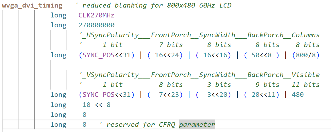
@ngeneer, just put in the P2 clock rate you want in the second long of the timing structure and the P2 clock to pixel divisor in the 5th long (shifted by 8) and keep the first long zero, then it will setup the PLL automatically. You don't need to mess with the clock mode anymore that way, as @evanh mentioned. You do need to setup the HSYNC and VSYNC longs for your desired video timing using your informaton then it should work. I'm fairly sure I have had it working in the past with a 7 inch Waveshare LCD so you should be able to get it to work too with any luck.
I expect from your data above timing would be something like this...but I'm not sure if it wants positive or negative sync polarities, so you might have to experiment with those (use SYNC_POS or SYNC_NEG). If 320MHz is too much for your P2 you could try 256MHz with a divisor of 8 instead. But that timing then only supports VGA analog output, not HDMI, which has to use a divisor of 10.
            long   0
            long   320000000
                   '_HSyncPolarity___FrontPorch__SyncWidth___BackPorch__Columns
                   '     1 bit         7 bits      8 bits      8 bits    8 bits
            long   (SYNC_POS<<31) | ( 40<<24) | ( 48<<16) | (40<<8 ) |(800/8)

                   '_VSyncPolarity___FrontPorch__SyncWidth___BackPorch__Visible
                   '     1 bit         8 bits      3 bits      9 bits   11 bits
            long   (SYNC_POS<<31) | (  13<<23) | (  3<<20) | ( 29<<11) | 480
            long   10<<8 ' P2 clock to pixel divisor (shifted 8)
            long   0
            long   0   ' reserved for CFRQ parameter
@ngeneer, just put in the P2 clock rate you want in the second long of the timing structure and the P2 clock to pixel divisor in the 5th long (shifted by 8) and keep the first long zero, then it will setup the PLL automatically. You don't need to mess with the clock mode anymore that way, as @evanh mentioned. You do need to setup the HSYNC and VSYNC longs for your desired video timing using your informaton then it should work. I'm fairly sure I have had it working in the past with a 7 inch Waveshare LCD so you should be able to get it to work too with any luck.
I expect from your data above timing would be something like this...but I'm not sure if it wants positive or negative sync polarities, so you might have to experiment with those (use SYNC_POS or SYNC_NEG). If 320MHz is too much for your P2 you could try 256MHz with a divisor of 8 instead. But that timing then only supports VGA analog output, not HDMI, which has to use a divisor of 10.
Thanks for that. I, for one, am glad you overdid the structure of the driver... I learned from it, in any case. Having all the variations built in makes sense for devices where you want to leave it open for anyone to plug in any external display they have. Maybe it'll take a push-button to cycle through the resolutions until the user finds one that works.
I've got a 7" touch waveshare display 1024x640 that is behaving nicely at the moment, too. I'll go back an monkey with the 4" on the next project.
@ngeneer said:
Thanks for that. I, for one, am glad you overdid the structure of the driver...
My complaint is it's under-done. The fields are too short, not enough bits allotted to important timings.
EDIT: That said, I probably would attempt to define the timing parameters differently. I've worked out that the hsync width, for both VGA and DVI signalling, can be preset to a fixed 64 dot clocks for all modes. And vsync width can similarly be fixed at 3 lines. Therefore, blanking totals, and dot clock frequency, are the only timing parameters to specify.
There's still a question mark on position of the syncs but generally the hsync is best centred midway along the blanking. Vsync I'm less sure of centring it or positioned at beginning of blanking.
@ngeneer said:
Thanks for that. I, for one, am glad you overdid the structure of the driver...
No worries.
@evanh said:
My complaint is it's under-done. The fields are too short, not enough bits allotted to important timings.
I did extend the structure after it was initially designed once I found it couldn't deal with wide blanking in some HDTV modes like 720p50 etc and this change probably wasn't well documented (or at all) at the time, but here is the relevant timing structure information that works with the latest driver.
EDIT: That said, I probably would attempt to define the timing parameters differently. I've worked out that the hsync width, for both VGA and DVI signalling, can be preset to a fixed 64 dot clocks for all modes. And vsync width can similarly be fixed at 3 lines. Therefore, blanking totals, and dot clock frequency, are the only timing parameters to specify.
Well I would say that this is an experimentally found result you might have discovered with whatever devices you have access to and tested, but I don't want to trust such third party results as being a way to simplify the code and instead would prefer to allow all values in the case what you may once have found no longer applies to some particular new/untested device someone else has. It's good to keep things as general purpose as possible IMO (within some actual real constraints of data sizes/bitfield widths used in the code itself). Obviously however it's a tradeoff as to what the best limits are, and not everything needs a long etc.
I found that method actually improved a number of modes. With VGA signalling, I could leave the monitor's position adjustment in the middle instead of the usual tweaking at the monitor. Eliminated the "It runs out of adjustment" problem. With DVI signalling, it seemed to provide a wider range of blanking. But that was likely monitor specific.
I think there is a total lack of info on what standard monitors and TVs actually use. I certainly don't trust the timing numbers we dig up from the web. VESA's published specs, for example, don't appear to be followed by anyone.
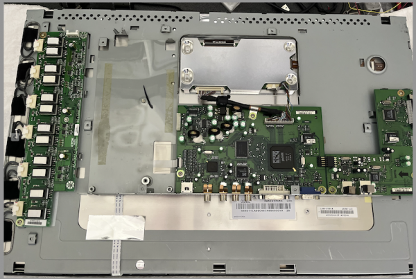
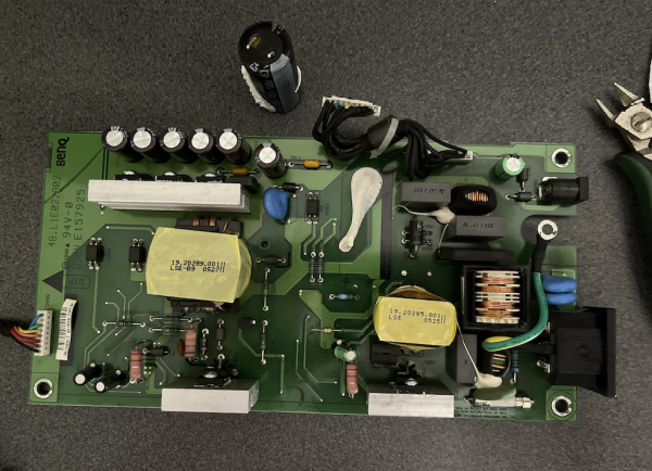
So I managed to get one of those 2405FPW Dell Monitors I use apart without destroying it in order to hopefully resurrect it (it has those extra composite/s-video/component inputs which makes it handy for my video driver testing).
Found evidence of a main 450V filter cap leak on one of its metal legs which is a common fault apparently (this is a 2005 product) so I cut it out and will re-order one from Digikey soon. Probed other active components and diodes etc and did a visual inspection and the rest seem good for now, although I may have missed something or it could be one of the PWM ICs on board too. This was the monitor that just seemed to not come back to life when it was already powered on and the power failure happened, after I returned to the room with the power back on to see what was working. Apart from the cap's electrolyte leak nothing inside it seems to have exploded from what I can see, unlike the other same Dell monitor which did explode when I first powered it up from the sleep state it had remained in during the AC failure. I hold out less hope for that one.
Hopefully I can get it going again...I am sort of in the market for a newer HDMI/Displayport monitor anyway but I know it won't have VGA or these other analog inputs, and the Dell's scaler on this is really nice. Actually turns out some of this was manufactured by BENQ according to the board's silkscreen inside. Who knew? The BENQ FP241W is a similar monitor but not identical.
Look for an open-circuit resistor connected to that capacitor. There's usually one for starting up the regulator and they are prone to going open-circuit from surges.
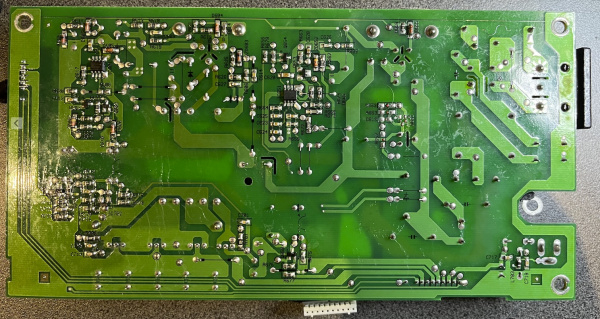
I can't see the PWM regulator IC. Is it on the other side of the PCB?
Yeah on rear side, here's the pic of that. I found some details of fixes for very similar power supply of 2407WFP on www.badcaps.net forums. If I had the full schematic of this board I'd be confident of a full fix with more probing.
EDIT: Why are these pics being downscaled to 600 pixels wide if I paste larger images to the forum? Didn't used to happen in the past.
Also found this repair video from a NZ guy with the same monitor.
There's a PFC corrector circuit that is prone to go bad but that seems to happen if the cap fails and goes open circuit and it takes out a current sense resistor and MOSFET/transistors etc which hasn't happened on my (1st) board. I tested the 120uF 450V cap which had leaked and it still reported 110uF out of circuit so I don't think it has fully failed but is definitely on the way out given the signs of electrolyte leakage, and the performance with ripple current present etc is probably pretty bad. It's going to be replaced. Other caps look okay but may need better testing.


Comments
What is the lowest vertical refresh for your monitor, can it do much less than 50Hz? That's where my monitors (both analogue and digital ones) seem to die, around 49Hz or so.
Yes, 49 to 61 Hz. But both the TV and newer monitor are happy with 24 to 75 Hz. Basically, displays that are newer than something like 2013 are much more flexible.
I have 2 Philips monitors at the university, both from 2020. One 27" which doesn't complain and displays 40 Hz, the second one, 24" doesn't like anything less than 49 Hz.
At home I have a cheap Chinese 15" TV and AOC 32" monitor which i didn't test for low vsync yet, but the TV doesn't like any non-standard VGA modes, including 50 Hz, while it accepts 50 Hz on HDMI input.
I'm only talking about behaviour with digital links, namely DVI and HDMI. Analogue VGA inputs are another story altogether.
This 24" Philips doesn't like <49 Hz on any input.
It'll be interesting to see its EDID data.
That's an idea. Package an Eval Board to extract EDID data from any HDMI display it's plugged into ...
For that you'd need to wire in the DDC wires and run some i2c over them. I think the breakout board exposes them on pads SDA and SCL.
Yup, that's how I've been gathering my data so far. I haven't used any Linux tools for extraction.
Just have to add Flash storage code now.
EDIT: Here's the EDID block read and emit to terminal - making use of Jonny Mac's low level I2C routines -
jm_i2c.spin2PUB emitblock( daddr, bnum ) : cksum | col, row longfill( @edid, 0, 128/4 ) ddc.start() ddc.write( $60 ) ddc.write( bnum >> 1 ) ddc.start() if not ddc.write( daddr & $fe ) if not ddc.write( (bnum & 1) << 7 ) ' 0 or 128 ddc.start() if not ddc.write( daddr | 1 ) ddc.rd_block( @edid, 128 ) ddc.stop() ser.str( string(" Device ") ) ser.hex( daddr, 2 ) ser.str( string(" Block ") ) ser.hex( bnum, 2 ) repeat row from 0 to 7 ser.nl() repeat col from 0 to 15 ser.tx(" ") ser.hex( edid[col + row*16], 2 ) cksum := 0 repeat col from 0 to 127 cksum += edid[col] cksum &= $ff ser.str( string(" Checksum ") ) ser.hex( cksum, 2 ) if cksum or bnum == 0 and (edid[0] or edid[1] <> $ff) ser.str( string(" failed",13,10) ) cksum := 1 else ser.str( string(" passed",13,10) )Cool, ticked that one off. I've converted all my EDID code over to C so then I could make familiar use of standard C file handling in FlexC using an SD card.
All went pretty smoothly. Would still like to add date stamping from a RTC but don't have the hardware on hand so have used a separate text file to specific the date instead.
I've tested it wandering around the house plugging into the remaining other displays. Discovered that pin9 of VGA connector, like pin18 of HDMI connector, can activate the EDID of attached display without any display power. Although, like everything about EDID, this don't always work.
PS: Gotta say that that
edid-decodeprogram is pretty cool the way it handles many encodings of the EDID data dump.EDIT: Attached the source code. What I do is put the compiled binary, named as
_BOOT_P2.BIX, on a uSD card and also create aDATE.TXTwith a date string that then is added to each dump within the report file. Pop the uSD card into the uSD slot of the Eval Board and connect the HDMI or VGA accessory - needs the SCL/SDA wires added as per above. And finally I plug in a USB battery pack to the AUX power input.[Updated source code attached]
Good effort. Could be handy to know a little more about a monitor this way by just connecting it directly to a P2 system, although that benefit is obviously going to be completely dependent on how accurate and comprehensive the vendors are when providing the monitor's EDID details.
Yeah, can't rely on the data.
The interest is partly to see how varied they are ... and partly to check out supposedly more modern monitors to see what the date of each EDID actually is. Looking at you, Pik, and that fussy Philips monitor!
Here's an update to the program using RCFAST for lower power running on battery.
[out-of-date, see below]
If the C is compatible with flexC you could port that EDID decoding code I posted earlier onto to the P2 as well and have the monitor display its own EDID information on screen for a full standalone thing. LOL, it could even use its own decoded information to build a timing for displaying of resulting data on screen, or just default to bog standard 60Hz VGA which is most likely going to be supported by the majority of monitors I would expect. Some P2 pins could be used as up/down switches to scroll through the data on screen if it takes up more than one screen's worth.
It did cross my mind, and I've not actually checked, but I'm quite happy with how it is. It's doing a little more than just the decoding too, not to mention the mode timings getting listed aren't a lot of use. They're just the boring known ones. The hex dump I collect can still be further decoded with that
edid-decodeprogram of course.One extra feature is the report includes a list of all responding device/bus addresses outside of EDID spec. This is a spill-over of example code of Jon's even. All bar one display, so far, has had multiple address ping responses. The old Dell DVI monitor is on its own in that respect. And that includes a couple of even older VGA-only monitors as well. I still have one working CRT, and an LCD from someone else's discarded fluorescent backlighting days.
The older Spin code I had, at one stage, also dumped blocks from those other device/bus addresses but the C code doesn't have that as yet.
Okay, a stumble later ... updated to also dump a block from each non-EDID ping.
EDIT: That's weird, I still had a bunch of Spin hexadecimals in the source code. I'm surprised they didn't cause compile errors ... okay, bug fixed those now.
EDIT2: And one
@address-of too. Also didn't cause a compile error or even a bug for that matter. It's almost like Eric has allowed both syntaxes in FlexC.I'm trying to configure p2textdrv0.93 (which appear to hold the matching p2videodrv files) for a waveshare 4" HDMI 800x480.
It would appear that I'm to add/adjust the code block that looks like this:
updated with values found on the Waveshare wiki like this:
and then add a 320MHz ? PLL clock setting here:?
Am I on the right track?
I don't know how to match up all the numbers from the waveshare data into the timing blocks nor how the bits are derived for the PLL.
Alternately... the VGA mode does appear to come out clearly in the textdemo, except that the display is rotated 90 degrees, starts about a third of the way from the left, and wraps around. I can't really tell if the WVGA modes are rotated or not.
using VGA mode would be suitable for me were it right-side-up ... if that is a known easy fix.
[rant mode]
Tell Roger to take that structure out back and gut it. He's got everyone jumping hoops to squeeze in the least number of bits for timings but then throws two whole longwords at the clock!
[/rant mode]
Okay, first helpful thing I'll say is the first longword is now depreciated. Just fill it with zero. That tells the driver to auto-compute the PLL clock mode from specified frequency in the second longword.
LOL. One day I might take a look but for now it's not a massive priority. There's a lot of one time configuration code that messes with that stuff that needs to change and be retested in order to alter it. Agree that minimizing the structure was pretty much an over optimization and it has become more complicated as I packed a couple of later features in as well. I did it when I thought I'd need a whole bunch of timings to be stored in the driver itself. I did include in some stock/common resolutions but then left it open to change by others for custom resolutions.
Also if it bugs you take a look at the provided API which can help create a custom timing for you without messing with the raw structure:
PUB createCustomTiming(timing, custompll, p2freq, divisor, hsyncpol, hfp, hsyncpixels, hbp, hcolumns, vsyncpol, vfp, vsynclines, vbp, vislines, breeze, colburst, cfreq) : rUnfortunately one bad thing that happened lately was an AC power glitch at home that took out both my well loved Dell 2405FPW monitors (one was on at the time and died immediately and the other exploded on next power up) which means right now I can't test composite, S-Video, and component sources anymore until I fix at least one of them (if they can even be fixed, hoping just the caps blew up).
@ngeneer, just put in the P2 clock rate you want in the second long of the timing structure and the P2 clock to pixel divisor in the 5th long (shifted by 8) and keep the first long zero, then it will setup the PLL automatically. You don't need to mess with the clock mode anymore that way, as @evanh mentioned. You do need to setup the HSYNC and VSYNC longs for your desired video timing using your informaton then it should work. I'm fairly sure I have had it working in the past with a 7 inch Waveshare LCD so you should be able to get it to work too with any luck.
I expect from your data above timing would be something like this...but I'm not sure if it wants positive or negative sync polarities, so you might have to experiment with those (use SYNC_POS or SYNC_NEG). If 320MHz is too much for your P2 you could try 256MHz with a divisor of 8 instead. But that timing then only supports VGA analog output, not HDMI, which has to use a divisor of 10.
long 0 long 320000000 '_HSyncPolarity___FrontPorch__SyncWidth___BackPorch__Columns ' 1 bit 7 bits 8 bits 8 bits 8 bits long (SYNC_POS<<31) | ( 40<<24) | ( 48<<16) | (40<<8 ) |(800/8) '_VSyncPolarity___FrontPorch__SyncWidth___BackPorch__Visible ' 1 bit 8 bits 3 bits 9 bits 11 bits long (SYNC_POS<<31) | ( 13<<23) | ( 3<<20) | ( 29<<11) | 480 long 10<<8 ' P2 clock to pixel divisor (shifted 8) long 0 long 0 ' reserved for CFRQ parameterThanks for that. I, for one, am glad you overdid the structure of the driver... I learned from it, in any case. Having all the variations built in makes sense for devices where you want to leave it open for anyone to plug in any external display they have. Maybe it'll take a push-button to cycle through the resolutions until the user finds one that works.
I've got a 7" touch waveshare display 1024x640 that is behaving nicely at the moment, too. I'll go back an monkey with the 4" on the next project.
My complaint is it's under-done. The fields are too short, not enough bits allotted to important timings.
EDIT: That said, I probably would attempt to define the timing parameters differently. I've worked out that the hsync width, for both VGA and DVI signalling, can be preset to a fixed 64 dot clocks for all modes. And vsync width can similarly be fixed at 3 lines. Therefore, blanking totals, and dot clock frequency, are the only timing parameters to specify.
There's still a question mark on position of the syncs but generally the hsync is best centred midway along the blanking. Vsync I'm less sure of centring it or positioned at beginning of blanking.
No worries.
I did extend the structure after it was initially designed once I found it couldn't deal with wide blanking in some HDTV modes like 720p50 etc and this change probably wasn't well documented (or at all) at the time, but here is the relevant timing structure information that works with the latest driver.
Well I would say that this is an experimentally found result you might have discovered with whatever devices you have access to and tested, but I don't want to trust such third party results as being a way to simplify the code and instead would prefer to allow all values in the case what you may once have found no longer applies to some particular new/untested device someone else has. It's good to keep things as general purpose as possible IMO (within some actual real constraints of data sizes/bitfield widths used in the code itself). Obviously however it's a tradeoff as to what the best limits are, and not everything needs a long etc.
I found that method actually improved a number of modes. With VGA signalling, I could leave the monitor's position adjustment in the middle instead of the usual tweaking at the monitor. Eliminated the "It runs out of adjustment" problem. With DVI signalling, it seemed to provide a wider range of blanking. But that was likely monitor specific.
I think there is a total lack of info on what standard monitors and TVs actually use. I certainly don't trust the timing numbers we dig up from the web. VESA's published specs, for example, don't appear to be followed by anyone.
So I managed to get one of those 2405FPW Dell Monitors I use apart without destroying it in order to hopefully resurrect it (it has those extra composite/s-video/component inputs which makes it handy for my video driver testing).
Found evidence of a main 450V filter cap leak on one of its metal legs which is a common fault apparently (this is a 2005 product) so I cut it out and will re-order one from Digikey soon. Probed other active components and diodes etc and did a visual inspection and the rest seem good for now, although I may have missed something or it could be one of the PWM ICs on board too. This was the monitor that just seemed to not come back to life when it was already powered on and the power failure happened, after I returned to the room with the power back on to see what was working. Apart from the cap's electrolyte leak nothing inside it seems to have exploded from what I can see, unlike the other same Dell monitor which did explode when I first powered it up from the sleep state it had remained in during the AC failure. I hold out less hope for that one.
Hopefully I can get it going again...I am sort of in the market for a newer HDMI/Displayport monitor anyway but I know it won't have VGA or these other analog inputs, and the Dell's scaler on this is really nice. Actually turns out some of this was manufactured by BENQ according to the board's silkscreen inside. Who knew? The BENQ FP241W is a similar monitor but not identical.
Look for an open-circuit resistor connected to that capacitor. There's usually one for starting up the regulator and they are prone to going open-circuit from surges.
I can't see the PWM regulator IC. Is it on the other side of the PCB?
Yeah on rear side, here's the pic of that. I found some details of fixes for very similar power supply of 2407WFP on www.badcaps.net forums. If I had the full schematic of this board I'd be confident of a full fix with more probing.
EDIT: Why are these pics being downscaled to 600 pixels wide if I paste larger images to the forum? Didn't used to happen in the past.
Also found this repair video from a NZ guy with the same monitor.
There's a PFC corrector circuit that is prone to go bad but that seems to happen if the cap fails and goes open circuit and it takes out a current sense resistor and MOSFET/transistors etc which hasn't happened on my (1st) board. I tested the 120uF 450V cap which had leaked and it still reported 110uF out of circuit so I don't think it has fully failed but is definitely on the way out given the signs of electrolyte leakage, and the performance with ripple current present etc is probably pretty bad. It's going to be replaced. Other caps look okay but may need better testing.
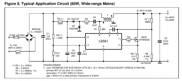
PFC chip
L6561
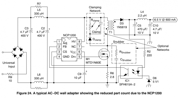
PWM chip
NCP1200AD60
R3 is the startup resistor for the PFC IC.
Wow, the regulator doesn't need any startup resistor. Pin8 accepts up to 450 volts directly!
Some people were posting full size multi-megabyte photos for no good reason. My guess is this is the quiet solution.
You can attach larger photos as a file to a posting and it should keep it intact. I'd like to get sharper photos of the PCB.
Ok, pity that it's extra work now to post any decent sized pics vs simple cut/paste.
Here are the pics of both sides in a larger format.