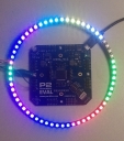
WS2812 smartpin driver
 ozpropdev
Posts: 2,793
in Propeller 2
Hi All
Here's a demo of a WS2812 driver using smartpins.
A table is generated in LUT of 24 bit patterns representing color byte waveforms.
A smartpin is configured in sync tx mode and fed with the LUT patterns.
The same sync tx smartpin gets its clock source from a neighbour smartpin configured in transition mode.
More "lanes" can easily be added(5 more of the same clock) by adding more sync tx smartpins.
{
Prop2 WS2812 demo using smartpins
Version 0.2
ozpropdev Feb 15th 2019
}

		sys_clk = 25_000_000
		us = sys_clk / 1_000_000
		ws2812_load = 51 * us
		_200ns = us * 200 / 1000

		num_leds = 64

		clk = 14
		ws2812 = 15

dat		org

		hubset	#0

		wrpin	#%1_00101_0,#clk	'transition mode
		wxpin	##_200ns,#clk
		dirh	#clk

		wrpin	##%1111 << 24 | %1_11100_0,#ws2812	'sync tx mode
		wxpin	#%1_00000 | 23,#ws2812
		dirh	#ws2812


'build ws812 waveform data into lut for each byte

'e.g. byte $8c becomes %001_001_011_011_001_001_001_011

		mov	index,#0
build		mov	count,#8		'number of bits
		mov	pa,index
		mov	pb,#0
.loop		testb	pa,#7 wc
		shl	pb,#3
		or	pb,#1			'0 = %100  (1/3 t)
	if_c	or	pb,#%10			'1 = %110  (2/3 t)
		shl	pa,#1
		djnz	count,#.loop
		shl	pb,#32-24
		rev	pb			'prepare for msb shifted first
		wrlut	pb,index
		incmod	index,#255 wz
	if_nz	jmp	#build


		getct	time
		addct1	time,delay


'Main loop

'send data to ws2812 devices

update_ws2812	loc	ptra,#@led_buffer	'iitialize pointer
		mov	leds,#num_leds
next_led	rdlong	rgb,ptra++		'get grb data
		mov	count,#3		'3 * 8 bits
next_color	getbyte	pb,rgb,#2		'get color byte
		shl	rgb,#8
		rdlut	pa,pb			'convert to waveform
		wypin	pa,#ws2812		'load sync tx with 24 bit waveform
		wypin	#48,#clk		'start 48 clock transitions
busy		testp	#clk wc			'wait for smartpin completion
	if_nc	jmp	#busy
		rdpin	0,#clk			'clear smartpin
		djnz	count,#next_color
		djnz	leds,#next_led
		waitx	##ws2812_load		'data low for >50Us

'shift led pattern in led buffer

		pollct1	wc
	if_nc	jmp	#update_ws2812

		addct1	time,delay
		loc	ptra,#@led_buffer
		loc	ptrb,#@led_buffer+4
		rdlong	pb,ptra
		rep	#2,#63
		rdlong	pa,ptrb++
		wrlong	pa,ptra++
		wrlong	pb,ptra
		jmp	#update_ws2812

time		long	0
delay		long	sys_clk  / 20

count		long	0
index		long	0
rgb		long	0
leds		long	0
lut		long	0


		orgh	$400

led_buffer
		long	$00_1f_00_00[4]	'green
		long	$00_00_1f_00[4]	'red
		long	$00_00_00_1f[4]	'blue
		long	$00_00_1f_1f[4]	'magenta
		long	$00_1f_00_1f[4]	'cyan
		long	$00_1f_1f_00[4]	'yellow
		long	$00_1f_1f_1f[4]	'yehite
		long	0[4]
		long	$00_1f_00_00[8]	'green
		long	$00_00_1f_00[8]	'red
		long	$00_00_00_1f[8]	'blue
		long	$00_00_1f_1f[8]	'magenta


Comments
Enjoy!
Mike
Smartpins make this so easy. A single cog can control a huge amount of leds.
BTW this is running in RCFAST mode with no problems.
Included is a Spin2 demo driving 51 strips of 60 leds at 32MHz.
Tested on a Eval board wuth PNut_v34o.
Or, just use the streamer for data directly. It doesn't use any external clock source anyway. Would have to format the multi-pin interleaved data pattern into hubram though.
A Spin2 example is here: forums.parallax.com/discussion/comment/1492328/#Comment_1492328
Andy
And it kind of obeys another behaviour of async serial too - A required gap for identifying the frame start. UARTs can't detect the start bit in a gapless stream.
Why do you think so? Here is a drawing that shows how the bits are encoded:
EDIT: BTW: Your diagram is so much easier to read than the datasheet I've downloaded.