Shop OBEX P1 Docs P2 Docs Learn Events
The Quby Game Console for Four Players — Parallax Forums

The Quby Game Console for Four Players

JRetSapDoogJRetSapDoog Posts: 954
edited 2018-10-07 15:56 in Customer Projects


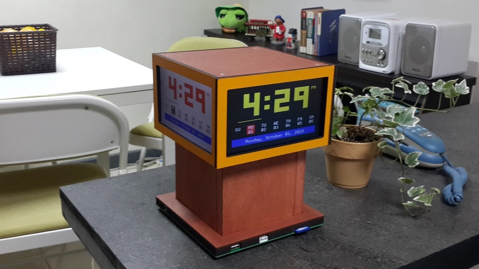
In this completed project, I'm announcing the Quby game console from WordFire (which is basically me). That's Quby, pronounced similar to the name Ruby (and like the letters "QB" for quarterback). Quby is a quad-screen clock and game console, which was primarily designed for word games. Games are stored on SD cards, and a few sample games are included on the provided SD card (though some polishing is needed).

If Quby seems familiar, it's likely because it's a revamped version of the Game-Time console that had a large food bowl for snacks. Quby gives up the snackbowl, but gains a cute form factor. Whereas the Game-Time console was somewhat bulky, Quby is comparatively svelte. The main reasons for the new version are that the old one was a complicated and costly build that was unsustainable at the discounted price I offered. So, I went back to the drawing board.

Quby is functionally identical to its "mother" (who retired after giving birth), running the same programs without change. In an improved design, Quby adds a power switch, as requested by forum members, and speaker mounts.

Since Quby's circuitry is essentially the same as the retired console's, if you have comments about how to add functionality and so on, perhaps you could post them on the other thread, as I'd like to keep this thread more focused on the design as it is. But other comments and feedback are welcome.

Also, per the guidelines for the rules about sales on this forum, if you'd like to purchase Quby, please indicate your interest here by a personal message (PM) or send me an email via the WordFire website, rather than doing so in a post on this thread.

For more information about Quby, please visit wordfire.net. The pages there, along with the videos for the retired console, describe Quby and its games. I haven't made a console overview video for Quby yet, but the brief intro at the top of this post lets you see the form factor. In the video, my main goal was just to announce the console and get the name out there, not provide a detailed treatment.

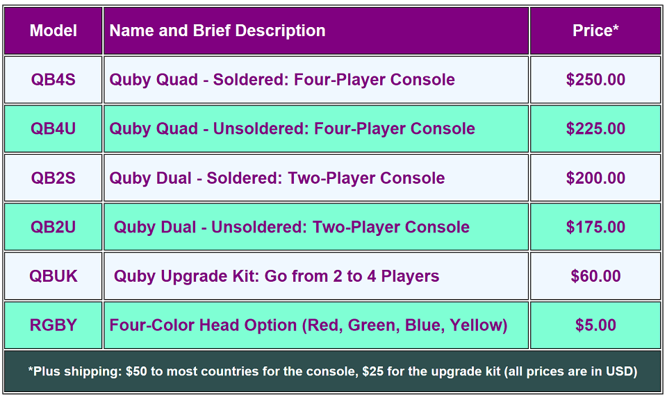
Regarding the website, see the Quby page for an overview of Quby, the Build/Soldering page for the soldering steps, the Assembly page for details about the housing, and, of course, the Buy page for ordering information. And for convenience, attached below is a screen capture of the pricing table from the Buy page, along with a couple shots of Quby.

Unlike last time, I haven't built a "fleet" of housings in advance nor ordered all the parts yet. So if you do order--and I hope that you do--please allow me a few weeks to order parts, build the units and ship them out. Payment would be through PayPal.

Meanwhile, thanks for reading. I have a flight on Monday, and I wanted to create this thread beforehand. As such, I may need a couple days to get back with you. But thanks in advance for any comments or feedback you provide. --Jim
960 x 540 - 169K
960 x 575 - 145K
960 x 540 - 158K
«13456789

Comments

  • Nice job on the new console! I hope it generates lots of sales. A four screen console is certainly a unique offering and you've done a nice job with the design.
  • Thanks for the encouragement, David. And thanks for following along with the console's development on the other thread.
  • JRetSapDoogJRetSapDoog Posts: 954
    edited 2018-10-12 02:59
    I made a video showing the Quby game console's form factor up close and personal. In the video, first, the head unit is opened up to reveal the LCD's, driver boards and cabling. Next, the base is removed to show the video cables that plug into the PCB on the bottom. Then, the cables are disconnected and reconnected. Lastly, the video shows how to access the real-time clock module to install a battery.

    The video might be useful to anyone interested in knowing how the cables are connected if one purchases an unsoldered version. It's pretty easy, as things are quite accessible from the bottom of the console once the base is removed. Just connect the four VGA cables and the four power cables, and then insert the real-time clock module. After that, tightening four screws fastens everything together. Though simple enough, it's nice to see things on video.

  • I watched it while it was posted and it seemed okay until about 3/4 of the way through the video froze and the audio continued. It seemed like the audio actually backed up because I think it described some of the video that had already played. Anyway, it was nice to see a tour through the guts of your new console. Thanks!
  • JRetSapDoogJRetSapDoog Posts: 954
    edited 2018-10-12 03:02
    Thanks, David. Yes, the first upload had problems. However, I re-uploaded the video to YouTube and that solved the problem. By the way, the last minute or so provides a real good look at the console.
  • Are you not concerned with the exposed PCB on the bottom?
  • JRetSapDoogJRetSapDoog Posts: 954
    edited 2018-10-12 19:29
    Hi, Dave. Yes and no. If I were releasing the console more widely, then yes. But so far, I haven't, and I figure people here on the forum know how to use it responsibly (meaning not setting it on top of their keys during operation and so on). I've sure seen a lot of boards with way more points of exposure than this console. I guess the fact that the rest of the console looks like a finished product and the fact that I made a website for it increases the expectations, so it gets graded on a tougher scale.

    Actually, I just got the PCB's back a tad over two weeks ago, and this form factor is a new design for me less than two months old (I believe). So I've been fairly busy with other aspects of the console. But two or three times over the last few days, I've briefly considered the matter of insulating the bottom. So it seems that your message comes at a good time. Still, I was busy tonight oven soldering PCB's, so I guess looking into insulating the PCB might get put off a few more days. I'd like to get a couple more units up and running first. I'm able to concentrate better by focusing on one main thing at a time, and I've found that problems tend to get solved when they need to get solved (not that I'm saying that one shouldn't try to look ahead and avoid problems with their designs, but often things happen in steps).

    Now in my own personal usage, I've never had an adverse incident of any kind due to the exposed PCB. The rubber feet elevate the console enough that it's likely to clear coins, metal rulers and the like. And I think it could even be used on a metal table without incident, but I wouldn't recommend it. By the way, I've touched many areas on the bottom of the PCB while powered with a bare finger without really noticing a tingle, though perhaps I would if I tried harder or my finger was wet. And the operation of the console seems largely unaffected by such touching with one glaring exception: touching one of the crystal pins, which will cause the console to crash, reset, lockup or otherwise fail (though cycling the power fixes that).

    The current base design was just the easiest, most straightforward way to build the console. As I believe I told David, who also mentioned his concern about the exposed bottom, I'm hopeful that I can attach a plastic or rubber or foam shield of some kind to the bottom to alleviate this concern. But I haven't tried that yet. I suppose I could have tried something along those lines in the same time that I've been typing this response. So maybe your comment will kick me into action. If such a shield doesn't work, though, then I guess I'll have to redesign the base such that it can be fully enclosed.

    But I hope that some sort of shield works. I've even thought about applying rubber or foam across the whole bottom and dispensing with the four rubber feet. Of course, the rubber feet also prevent the pointy leads from the through-hole components from scratching whatever surface the console is setting on. They also elevate it off of a surface that might be wet (a beverage could spill during game play, for example). So, what I may do is keep the feet and work a shield around them. But I just haven't wrestled with this matter beyond that. But figuring this out is on my "To-Do" list, and I wouldn't want to publicize the unit much further without coming up with a solution.

    I like the phrasing of your question, which begins with "Are you not concerned...." The likely implication is that I should be concerned. I suppose a "You're not concerned about...." would be slightly stronger but similar in impact. Well, mark me down as being concerned = put me in the concerned camp. And although I hope there are some things that you like about the console, thanks for bringing this matter up. I'll try to get on the problem next week, and will definitely seek some kind of solution if I ever try to take the console to the next level. But it's been pretty hard for me just to get it to this point.
  • kwinnkwinn Posts: 8,697
    @ JRetSapDoog

    I have often used a sheet of plastic such as the file separators or document covers available at Staples to protect the bottoms of PCB's. They are easy to cut to size and punch holes in, as well as very inexpensive.
  • Thanks, Kwinn. I might try that. I was thinking of something stiffer/thicker, similar in consistency to those flexible plastic three-ring binder covers (Polyvinyl Propylene or PP), which I can buy down the street in large sheets. But perhaps it's overkill. Maybe the stiffer document covers that you mention would do the job. I use thin PP or ABS (plus tape) to prevent the driver boards from shorting out on the backs of the metal LCD's. Of PP and ABS, I prefer the PP, as it's softer or more pliable and seemingly less brittle or subject to cracking (though I've used both = whatever I had on hand). Yeah, need to experiment. I'm not sure how well the four mounting screws I use would hold such sheets around the periphery. Maybe I can use some double-sided tape, too. Hopefully, I won't need additional hardware. Perhaps tape is the way to go if the existing screws don't suffice. Anyway, it's good to know that you've used the plastic material you mentioned for providing protection for PCB's. That makes it seem less unorthodox.
  • Thanks, Kwinn. I might try that. I was thinking of something stiffer/thicker, similar in consistency to those flexible plastic three-ring binder covers (Polyvinyl Propylene or PP), which I can buy down the street in large sheets. But perhaps it's overkill. Maybe the stiffer document covers that you mention would do the job. I use thin PP or ABS (plus tape) to prevent the driver boards from shorting out on the backs of the metal LCD's. Of PP and ABS, I prefer the PP, as it's softer or more pliable and seemingly less brittle or subject to cracking (though I've used both = whatever I had on hand). Yeah, need to experiment. I'm not sure how well the four mounting screws I use would hold such sheets around the periphery. Maybe I can use some double-sided tape, too. Hopefully, I won't need additional hardware. Perhaps tape is the way to go if the existing screws don't suffice. Anyway, it's good to know that you've used the plastic material you mentioned for providing protection for PCB's. That makes it seem less unorthodox.
    I'm tempted to try using a piece of plexiglass with standoffs held on with the four mounting screws on my old model. That way you'll still be able to see the PCB through the plexiglass. I guess the interesting parts are on the top side though so maybe it isn't worth the effort.

  • Yeah, transparent material is an option. You may need longer screws if you try that. I'm waiting for you to come up with a solution, then I'll copy it. :nerd: By the way, "old model" can be recast as "vintage/classic model" or "the snack bowl edition." :smile:
  • When you post an announcement of this console on another forum could you put a link here so we can follow whatever interest it generates? We need to expand our little community of WordFire/Cuby users!
  • I'll probably do that; however, I haven't yet made any specific plans for announcing Quby beyond the forum. Hopefully, that time will come, as I think that there could be more interest with a more general audience. Of course, those folks are less likely to be interested in programming the console. Anyway, right now, I'm putting together a little soldering guide video that I hope to post soon.
  • I think you mentioned a while back that you did a case design that looked like a truncated pyramid. Do you have any pictures of it? Why did you decide against it?
  • Hi, David. Yeah, that was a working prototype. It used lower resolution screens and drove them with composite video (three pins per screen) instead of VGA video. I have pictures held captive on my dead desktop and no doubt backed up on DVD's or maybe SD cards. And I still have the console itself boxed up somewhere, so I could take more. But it's not in an operational state, as I cannibalized the EEPROM (and it would take time to dig up the files to reprogram it). So, I'd have to search through backups to see if I could find pictures with the screens lit up.

    However, I think it's best not to post the pics here, as I don't want to "pollute" this Quby thread too much. Perhaps some day I can add pics of it to the Pics page of the website, as that page already shows some of the old console designs. Anyway, it was just a truncated pyramid (called a frustum), about 11 inches at the base and 7 or 8 inches at the top, standing about 5 1/2 inches high or so. And it had a recess in the top for inclusion of a small snack bowl.

    As to why I moved away from that form factor, it was rather difficult to build. And in that the four sides obviously didn't form a 90 degree angle with the horizontal PCB in the base, it was more difficult to bring out the ports. Also, in my opinion, the stand-based consoles look better. Lastly, one needs to tilt one's head less to view the screens with the latter designs. While the frustum form factor seemed ideal to me at the outset, it proved to be problematic (though perhaps it could work in a smaller version in combination with a board game). So, I wish I had started with the current form factor. As they say, "Think outside the frustum."

    In other news, I finished editing a soldering video for Quby's PCB and am uploading it now. I hope to post it in about eight hours.
  • Thanks for your comments on the pyramid version. I guess I can see why you moved away from it. Adding pictures to a "History" page on your web site might be nice some day but, as you say, you don't want it confusing people by adding them to this thread where you're trying to promote your current console. Just the dimensions that you mention give me a pretty good idea of what it looked like anyway.
  • I wonder why you moved away from the composite screens. My "theory" is that these "random" LCD driver boards have horrible composite decoders that make the text hard to read. I'd love to know whether these driver boards are as bad as I assume (from experience with older flat-panel TVs), in terms of composite decoding.
  • The text looks pretty good on mine.
  • JRetSapDoogJRetSapDoog Posts: 954
    edited 2018-10-20 16:33
    You may be on to something there, Wuerfel_21. I wasn't so satisfied with the quality of the text from the driver boards (back then) when driven with composite video. The text tended to shimmer. Sometimes there were artifacts. And screen brightness tended to vary from screen to screen. It wasn't so bad, but it's nothing like the VGA setup now, which seems rock solid. For the current driver boards and screens, it's been a long time since I've driven them with composite video, so I'm not sure how much they improved things, if any (meaning, I've forgotten). But I really like the VGA performance. Now, of course, the console doesn't try to anti-alias the text nor use a proportionally-spaced font, but it looks good enough for the use case. And a fixed-width font has some advantages for certain text games. But back to composite video, I like the video that the Parallax Demo Board, for example, produces when viewed on a ~10" or so monitor, but such composite video can look a little "anemic" on a 7" screen. By contrast, VGA text is pretty crisp.
  • Wuerfel_21Wuerfel_21 Posts: 4,351
    edited 2018-10-20 17:14
    The shimmering happens when the number of PLLA clocks per frame isn't a multiple of 16. The artifacts though, are unavoidable. PAL composite has less of them (and higher resolution), but has some clock jitter issues when generated by a Prop @ 80MHz.

    RGB of course has none of those issues, but 8 colors are somewhat meh. Fine for text I guess.
    A P2 version would of course jam some sweet truecolor up on those screens.
  • Jim: Do you have a video driver that supports a visible cursor? It could either be a flashing block or underscore.
  • JRetSapDoogJRetSapDoog Posts: 954
    edited 2018-10-20 23:21
    Hi, David. No, I don't. But I recall experimenting with one in the past. Of course, such a cursor implementation should work for all four screens. So, one can add code to make a cursor flash in the main loop that handles a game, just like code to update a countdown timer or do some sort of animation. That is, the code doesn't have to be in the video driver itself that kuroneko developed (though that might be nice). So, one can just repeatedly output the cursor character followed by a space (or other blank redefined character). However, one has to be careful to handle backspace properly (if providing backspace functionality, that is), such that the cursor isn't flashing in the wrong position or doesn't leave "ghost" cursors behind (either in front of or behind it). By the way, perhaps a better way to handle cursor flashing would be to continually redefine a single font character as the cursor. Then it would "automatically" update all four video instances each time the font data was changed (of course, you'd just want to use such a character only once per screen to avoid having multiple flashing cursors on the screens).
  • Below is a video that walks one through soldering the Quby printed circuit board (PCB). The 20 steps of the video mostly correspond to the steps provided for soldering Quby under the Build tab of the website. The video should be of interest to anyone considering buying the unsoldered version of the Quby console. It may also help curious onlookers better understand how the console works, and they may learn something by watching it. Originally, I recorded the whole process of me soldering up a board, with the intention of doing a time lapse (sped-up) video. However, I decided it was likely better to just to do a summary of the process using a soldered PCB.

  • JRetSapDoogJRetSapDoog Posts: 954
    edited 2018-10-20 23:40
    Thanks for that information, Wuerfel_21 (sorry for the late reply, as I originally missed your post). Those things are good to know. Perhaps the driver boards themselves also introduce a bit of "noise." Yes, the composite video version allowed for more color combinations (though many of them were similar). Regarding shimmer, it is especially present when the font characters being used aren't three pixels wide. Most of the Parallax font characters are three pixels wide for all their various strokes, but some of the electrical symbols in the font are not. The coil and capacitor characters shimmer quite a bit, but you kind of have to be looking for the shimmer to really notice it (unless the screen has a lot of such characters).
  • Another possibly interesting thing: If you really want to nickle-and-dime those pins, you could also check/try if your screens support CSYNC instead of seperate HSYNC/VSYNC. That would give you one pin for uuhmm.... something?
  • JRetSapDoogJRetSapDoog Posts: 954
    edited 2018-10-21 00:13
    I tried to look into whether the driver boards supported sync-on-green (SoG) once, as it saves the most pins, but didn't conclude anything definite. I think I even tried to do some kind of test once, but I doubt that I altered the video code appropriately to really test correctly. Anyway, the current driver boards use the Realtek RTD2660, which is quite popular for these small driver boards. I skimmed over a big datasheet (or manual) for it once. There's more stuff in there than I realized (no surprise there). I think some (or all?) of their chips can handle component video (YPbPr), for example, but, of course, that doesn't mean that the specific driver board maker using such chips has wired up a connector to take advantage of that. The situation with HDMI may be similar.
  • Below is a video that walks one through soldering the Quby printed circuit board (PCB). The 20 steps of the video mostly correspond to the steps provided for soldering Quby under the Build tab of the website. The video should be of interest to anyone considering buying the unsoldered version of the Quby console. It may also help curious onlookers better understand how the console works, and they may learn something by watching it. Originally, I recorded the whole process of me soldering up a board, with the intention of doing a time lapse (sped-up) video. However, I decided it was likely better to just to do a summary of the process using a soldered PCB.

    Nice job on the video! I think you could probably let the buyer solder the SD socket as well. Even though I'm not that comfortable soldering SMD parts, I've never had trouble with a full size SD socket.

  • Hi, David. No, I don't. But I recall experimenting with one in the past. Of course, such a cursor implementation should work for all four screens. So, one can add code to make a cursor flash in the main loop that handles a game, just like code to update a countdown timer or do some sort of animation. That is, the code doesn't have to be in the video driver itself that kuroneko developed (though that might be nice). So, one can just repeatedly output the cursor character followed by a space (or other blank redefined character). However, one has to be careful to handle backspace properly (if providing backspace functionality, that is), such that the cursor isn't flashing in the wrong position or doesn't leave "ghost" cursors behind (either in front of or behind it). By the way, perhaps a better way to handle cursor flashing would be to continually redefine a single font character as the cursor. Then it would "automatically" update all four video instances each time the font data was changed (of course, you'd just want to use such a character only once per screen to avoid having multiple flashing cursors on the screens).
    Good point. In fact, I guess I could just display an underscore where the cursor is supposed to be and not even bother flashing it at least as a first attempt.

  • Wuerfel_21 wrote: »
    Another possibly interesting thing: If you really want to nickle-and-dime those pins, you could also check/try if your screens support CSYNC instead of seperate HSYNC/VSYNC. That would give you one pin for uuhmm.... something?
    It would be nice to free up a couple of pins to let the WordFire/Quby board talk to an external processor like the PIC32. That would open up more complex games than can fit on the Propeller.

  • Perhaps Quby could do that intercommunication now (with some programming work on the host and slave ends) with what's already been provided with the expansion pads. However, I don't want to go down this path too far and derail things as in the other thread. As for games that will work on the console, I have more ideas than time to develop them. On the one hand, the potential for word games seems unlimited; but on the other hand, there are limits. It's kind of like how there are different "sizes" of infinity. While some of the complex games you may be interested in wouldn't work, I have many ideas for word games that will work just fine on the console (and some games that are not word-based will work, too). Hopefully, this thread can focus on games for the console, so, if and when I come up with anything new, I'll try to post an announcement here. I hope that you folks will, too.
Sign In or Register to comment.