Ternary Video DAC for More Colors
 SaucySoliton
Posts: 557
in Propeller 1
The standard Propeller composite video output circuit consists of 3 resistors of 270, 560, and 1000 Ohms. When connected to 3 output pins this circuit is able to produce 8 distinct output voltages. This is what we expect because 2^3 = 8.
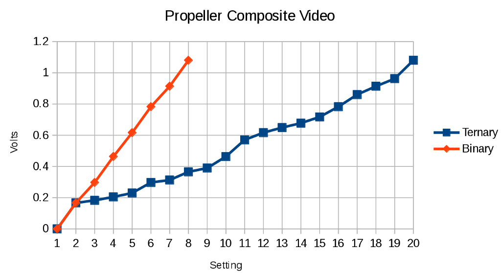
The good: If we add high impedance to the output high and output low states used previously we have 27 unique output states. ( 3^3 = 27 ) There are 8 states that result in 0 volts at the output. In total, we have 20 unique output voltages possible from the circuit.

The bad: The linearity is not so good. It's not obvious how to generate the output state for a given voltage. The easiest way is to compute all 27 states and sort by voltage. A look-up table can solve both of these at the same time. :cool:
The ugly: The video generator doesn't drive DIRA. We would have a bit-banged video driver. It would be best to update DIRA and OUTA simultaneously. One way to do this would be to use one cog for the output high and another for the output low. That way they can have OUTA constant and just update DIRA. They could read the same data and just use a different look-up table. We would have to generate the chroma subcarrier in software. On the bright side, the 80MHz system clock would give more phase resolution than the 16x clock used by the video generator.
Implementing this in the P1v would solve most of the uglies. We could just modify the video generator to let it drive DIRA as well as OUTA. But, without a proper PLL the P1v likely doesn't produce such good quality video.
If I missed a previous discussion about this, please let us know.
The good: If we add high impedance to the output high and output low states used previously we have 27 unique output states. ( 3^3 = 27 ) There are 8 states that result in 0 volts at the output. In total, we have 20 unique output voltages possible from the circuit.

The bad: The linearity is not so good. It's not obvious how to generate the output state for a given voltage. The easiest way is to compute all 27 states and sort by voltage. A look-up table can solve both of these at the same time. :cool:
The ugly: The video generator doesn't drive DIRA. We would have a bit-banged video driver. It would be best to update DIRA and OUTA simultaneously. One way to do this would be to use one cog for the output high and another for the output low. That way they can have OUTA constant and just update DIRA. They could read the same data and just use a different look-up table. We would have to generate the chroma subcarrier in software. On the bright side, the 80MHz system clock would give more phase resolution than the 16x clock used by the video generator.
Implementing this in the P1v would solve most of the uglies. We could just modify the video generator to let it drive DIRA as well as OUTA. But, without a proper PLL the P1v likely doesn't produce such good quality video.
If I missed a previous discussion about this, please let us know.


Comments
Yes you're right P1V would make it easier to implement
Can you post a state table showing all values, including zero values?
-Phil
Edit: Synchronizing the two PLLs might be a little tricky.
Another option could be to trade resolution for colors. Imagine you want a color display in 320x240. So you setup display of resolution 1280x960. Each color is active low and connected to a capacitor through some resistors and a diode. When the pixle switches low, it discharges the cap through the resistor. As the four pixles go by the capacitor dicharges. Every four pixles, there is a clock pulse , active low, from a timer. That rapidly discharges the capacitor, it just connects directly to the pixle through a diode. There might be a rainbow effect across the pixles, but it should either together into a friend of color since the pixles are small. You could also reduce the bandwidth of the monitor with an extra filter across the color pins if needed.
So now, with the "typical configuration" of 2 lines per color, and two for h and very sync, you can choose (just not all at the same time) between 64 colors. So you blend 4 64 color pixles together. Or perhaps bit bang v sync and use a timer for h sync , allowing all 8 lines to be used for color. You won't get the full range of colors for the bits your sending, but it will be more than you would have without it. If your carefill you might be able to exploit the charging curve of the capacitor.
It's easy to see though, some color values are degenerate. Consider a simple two color non indexed system. So each pixle is just on or off, and set to black and some arbitrary color via a resistor. Consider averaging only three pixles. We have 4 colors. Off, 1 bit period discharge, 2 bit period discharge and 3 bit period discharge. So 001, 010 and 100 are the same color, as are the 011,110,101. Maybe adding a discharge resistor might help, so that 001, changes say to 1/3, then discharges 1/4 per pixle. The spacial extend of the "rainbow" effect might change theperceived color as well.
Changing the load resistance can cause the ordering of the states to change. This could be inconvenient for some applications. But who really wants to complain about extra output voltages? The Propeller color chart looks good already, but it could use more gray levels. It might be reasonable to modify DIRA to get different grays.
I've attached the spreadsheet to everyone can play.
In addition to adding the ability for the video generator to update DIRA, you'd need to modify the WAITVID instruction to add a CLUT between the color bytes and the video generator.
But the 3 bit DAC isn't the limitation for NTSC colors - my 240H sprite driver has a gamut of 172 colors by clocking the video generator at 4x colorburst and generating the color signal directly. The real issue is how the video generator creates color with +1/-1 on the luma value. You'd need to provide additional options for the color intensity to have any real impact. Otherwise you're just increasing the number of grays rather than the number of colors.
You may also be interested in https://forums.parallax.com/discussion/126099/more-colorful-baseband-tv
I found a simple rule to generate the ternary dac states: For binary states 1-6, setting DIRA to the same value as OUTA will add a half step. (Instead of outputting low, tri-state the zero bits.) As before, the ordering changes when the load changes.
I think increasing the number of gray levels is useful. Although I probably won't do anything with this work. It's amazing that after over 10 years that there are still tricks to be found.
As I mentioned, the main limitation is how the color signal is generated as luma +/-1. My idea is to make more effective use of the color byte and expand the range of color saturations.
$00 - $07 would still drive the DAC directly to produce sync and 6 shades of grey. However, instead of using $x8 - $xF for color, instead use $1x - $Fx, with the most significant nibble selecting high and low output values which the phase generator would then alternate between.
One other enhancement I would suggest is to use VCFG[31] to select between adding and subtracting the phase portion of the color byte from the phase counter. This would then be used for PAL to alternate the color phase between lines rather than performing the ones complement on the color byte.