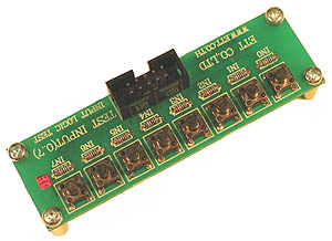
Push Button Test Board and Basic Stamp 1
 microcontrolleruser
Posts: 1,194
in BASIC Stamp
Same routine as LED Output board.
1 Figure out which way 10 pin IDC connector is oriented.
2 Test it
Here's link to the board. Will post picture of board.
http://www.futurlec.com/Input_Pushbutton.shtml


Comments
Here's the code forum member Tom contributed to test the board.
You might give a look at the "BUTTON" command in the Stamp Syntax and Reference Manual on pages 137 - 140.
It comes in handy if you wish to debounce the switch.
Also, page 139 has a sample program for the BS1.
Debounce!!!??
Ooh! Make it go away!
One tutorial for micro's Stamps are made from had big section on debouncing.
It was nightmarish.Fortunately we are using a different book now.
That other tutorial was college level.
Current one just covers 'most' aspects of that micro and then you're ready to go fumble around on your own.
Sort of equivalent to doing What's a Microcontroller all the way through.
Not too light. Not too heavy.
If you click on Pbasic 2 or 2.5 AND Stamp 1 it throws an error message.
Been using PINS.
Do we need PIN for something?
Oh.I see.The Tom Crawford code.
No worries.We can jump over to Stamp 2 board.
Long as it tests for logic 0 on a pin.
PIN is only supported by PBASIC 2.5 which the BS2 uses.
I think the BS1 uses SYMBOL.
Thanks.
Will sidestep that added process.
Use Tom code with Stamp2 BOE.
Took Stamp2 module off of breadboard and back onto BOE.
Testing it now.
9v battery is a good idea.Reduces cable clutter.
It identified good.
Warning! Side project.
Let me test Stamp 1 project board with Startech Serial to USB and Parallax one.
This BOE showed yes Loopback and Echo.
I think the Startech was zero on both.See if Parallax is better.
Okay. Startech show no loopback and no echo.
Let's see what Parallax USB to serial does.
Okay.Parallax is no loopback and no echo.
Maybe it's the board.
It programs and debugs with terminal okay
See Table 3.5 in the BigYellowBook.
What is the Big Yellow Book?
Can you say why the Stamp 1 project board shows Loopback no and Echo no?
https://www.parallax.com/downloads/basic-stamp-manual
Thank you Publison
Never heard it called that before.
Will take a look.
First order of business is to figure out pinout on push button board 10pin IDC socket.
Probably upside down from the diagram like the LED board.
It does have a lug on socket to orient cable but we're not using a cable.Using jumpers into it.
Will work on code in a bit.
Push button experiment in 'What's a Microcontroller'.
Nice 'build up' approach.
Tests circuit electronically only without code.
First code is debug pin routine.
Then adds decision code to light LED out other pin.
Nice tutorial.