Directly driving Nema 8 stepper motor with the Propeller
 Tubular
Posts: 4,771
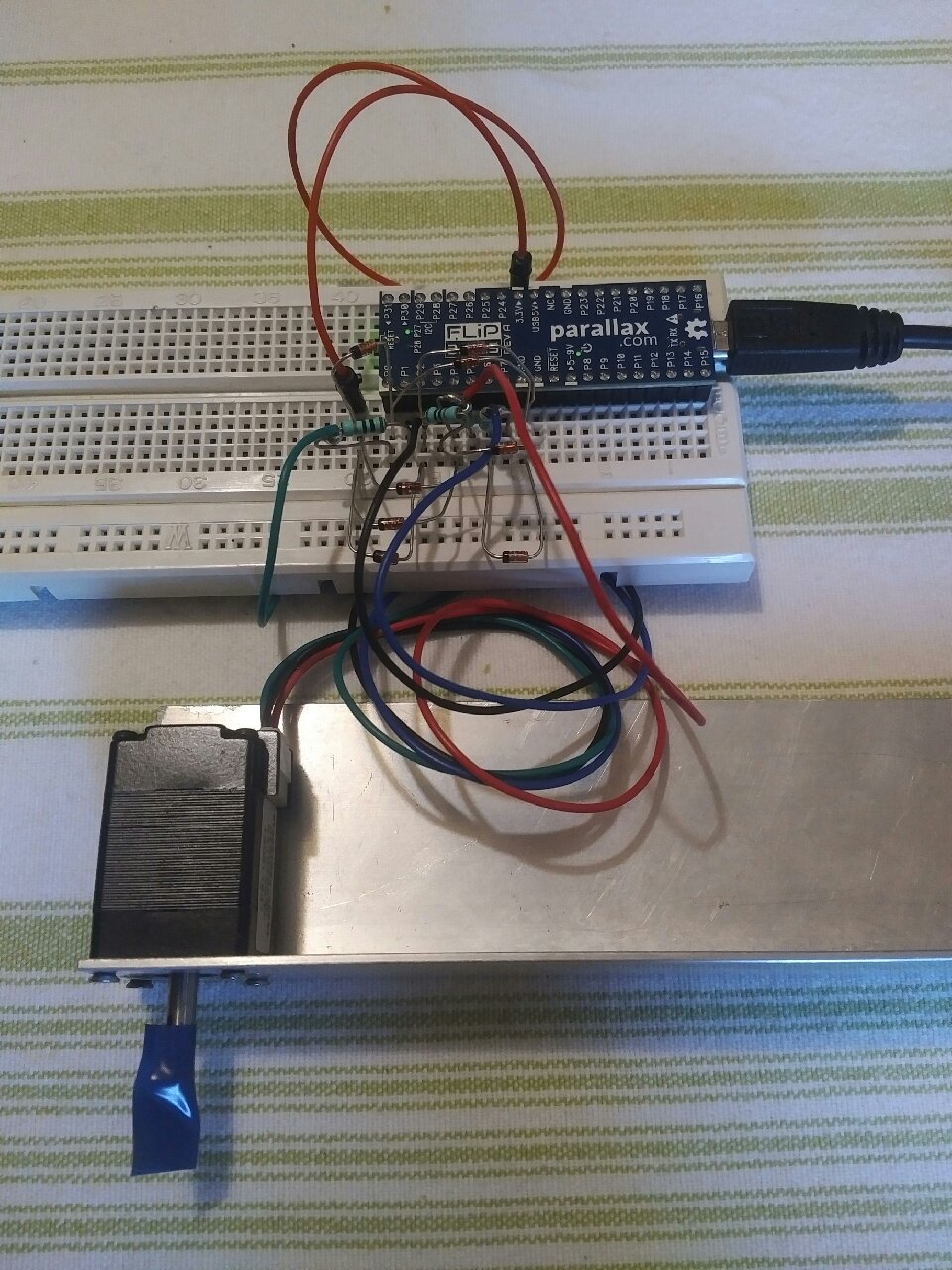
The recent cnc/gcode threads reminded me to try this, and once again the Propeller hasn't let me down. This is an 'educational' demo of a couple of H-bridges constructed from bare propeller io pins.
To get enough current to rotate the motor, two pins drive each leg of the bridge, so 8 pins for the 2-phase stepper. There is a 10 ohm resistor between them to limit the current slightly, should the pins not accidently be driven simultaneously (prop fet switch resistance is ~ 28 ohms, the two including 10 ohm make an approx 16 ohm switch).
As you'd expect, the torque produced isn't amazing, but you could use more io to strengthen, or find a stepper with higher coil resistance (this one is from pololu and has about 8 ohm phase resistance). However for demonstrating basic rotation and perhaps some concepts like micro stepping and loss of sync, its going to be good enough.
Hoping to run 3 demo axes from a single prop, we'll see.
Heres photos and a vid. Will post code shortly, want to double check currents so I don't blow up a whole lot of other peoples props.


Comments
https://www.dropbox.com/s/c6yiq779l2hhfb9/MOV_20170620_0105468.mp4?dl=0
When I was looking at propeller resistive DAC arrangements some time ago, I remember noting the max current with an external 1 ohm resistor (across 2 pins, 1 output high, 1 output low) was only just over the 40mA abs max, due to the N and P fet resistances ~28ohms, and lowering the rails slightly might be enough to get under that
Agreed re spikes though. I'm going to look at some better diode options shortly
   outa[12]~     '                   measure 14mv rise off ground on this pin
   outa[13]~     ' 7.5 ohm resistor  measure 1.661v at this node
   outa[14]~~    '  between P13&P14  measure 1.960v at this node
   outa[15]~~    '                   measure 19mv droop from 3v3 on this node
                 'Calcs:-
                 ' Res current=(v14-v13)/7.5 ohms = 39.9mA
                 ' P fet resistance 1.297v/39.9mA = 32.5ohms
                 ' N fet resistance 1.661v/39.9mA = 41.7ohms
My other question is, since all the voltage action is around that narrow central range (1.6~2v), couldn't I clamp the spikes to a different rail (eg an actively driven midrail, or blue led clamps down to Vss/up to Vdd). That would relieve the P1 ESD diodes, right?
All MOSFETS look like resistors at saturation,and current sources/sinks, when well away from saturation.
Most MCU data sheets give curves showing this.
You could use schottky diodes to clamp better, and could parallel more pins for higher drive, but the question remains.... Why ?
The P1 has one of the highest cents-per-IO price of any MCU, so using the pins on a P1 to save a 3c mosfet seems illogical ?
this approach (*), and doesn't need 8 schottky diodes either!
Direct drive for one of the 6mm sized steppers is more reasonable (they are typically used in
auto-focus mecanisms etc, and cheap on eBay). Even those like 75mA or so which is well above
a single pin drive, but are a good match for 3.3V
(*) more torque, much higher top speed, allows microstepping...
You want to sell this design?