Making a PCB from a Circuit Overlay Board design
 David Betz
Posts: 14,530
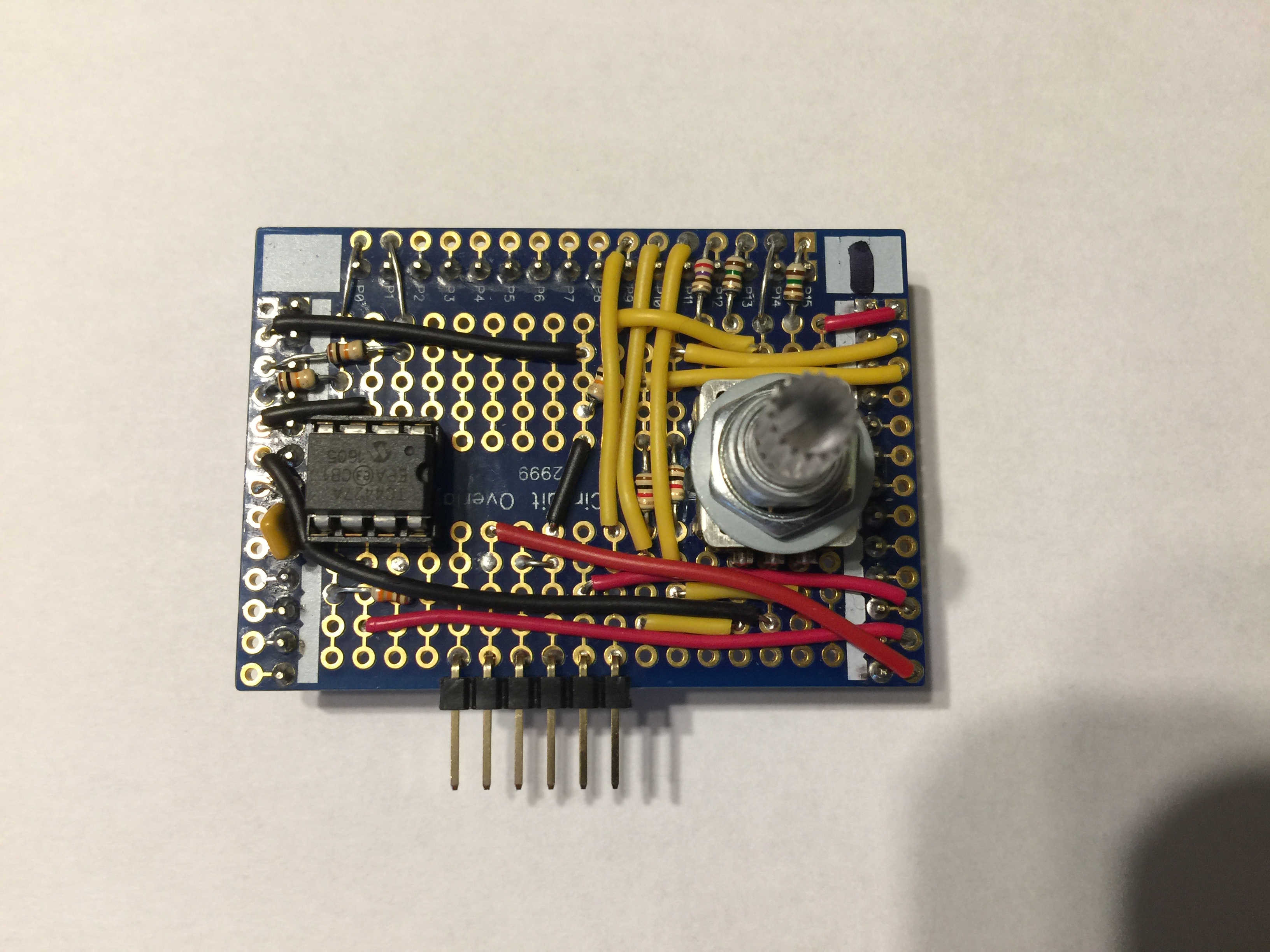
I've finished a simple NeoPixel gadget using a strip of NeoPixels, a Parallax 16x2 LCD display, and a rotary encoder. It also uses JonnyMac's TC4427 circuit for interfacing the 3.3v Propeller pin with the 5v NeoPixels. I built the thing on a Parallax Circuit Overlay Board that plugs into the headers on an ActivityBoard. Now I'd like to try my hand at making a PCB. My idea is to start with the design files for the Circuit Overlay Board and then remove the generic traces from the center and replace them with my circuit. I guess I need to do this with DipTrace since that is what the Parallax design files are for. If that works, I'd like to take the design for the Prop Mini and add my circuits to make a complete standalone board. This isn't really a practical product but I thought it would be a chance to try to make my first PCB. Does this sound like a reasonable approach?


Comments
than ExpressPCB Mini Board Service.
Of course; I was thinking of the standard boards, (2 x 3).
-Phil
PM sent
I used these to create an overlay for a customer. Note that I extended the bottom of the PCB so that I could put small pots on the board. I ordered the boards from inside DipTrace though this not what I typically do; they put they're own marks on the boards (these are prototypes, so it's not a big deal), and I don't think their solder mask is great. For boards that I really care about I order via www.goldphoenixpcb.com.
http://pcbshopper.com/
See some related info on this thread.
There are mixed opinions about DipTrace on the forum, which is fair. For my simple needs, I rather like it. Have fun!
Check DipTrace files for any and all Propeller board designs that are available now. You may not need the PropMini files.
These were my efforts with hacking up the Quickstart board: http://forums.parallax.com/discussion/145262/what-to-put-on-a-propeller-quickstart-layout-that-has-wide-open-spaces
Did you save the schematic after making changes? If yes, then inside the PCB program you need to refresh the link to the schematic to bring in the new parts and nets. You can find this in the File men. The first time you do it with a given schematic (even one provided for you), use
File -> Renew Layout from Schematic -> By RefDes...
With this selection you'll need to select the schematic you want to link to the board. Once that's done you can make changes in the schematic (remember to save the file), then do a quick refresh inside PCB with Ctrl+Alt+U.
I do this all the time. I have a starter schematic that we use for most EFX-TEK products (power, propeller, eeprom). I save this to a new project, save the blank board to a new project, link them, and then get to work.
If something simular to this protype ends up as an efx-tek product count me in!
JonnyMac awesome article in the latest NV. Always learning something new from your column.
Last time I tried DipTrace on Wine was a year or so ago, but I do recall issues with the graphics. I can't totally remember if that was a Wine or VirtualBox thing, but anyway DipTrace really struggled without direct access to the video card.
Seemingly VirtualBox / Wine added an intermediate layer- some sort of virtual video driver possibly. Thinking about it now, VBox certainly uses virtual drivers so I'd expect running any sort of CAD or graphics software on Win in a box will be problematic. Oh, and now I recall that Wine (on Ubuntu) was my first choice, but that failed worse than running Windows DipTrace in the VBox!
At the time, I experimented briefly with adding a second video card just for VBox, but time ran out before I got anywhere with that idea.
Overall experience- I think the schematic was ok, but the pcb layout and especially 3d rendering was unreliable. Random crashes and freezing- that type of thing.
That said, VBox may have improved since then- IMO, direct access to the host video card is going to be the crucial thing.