Techniques for reverse engineering data stream
Hello,
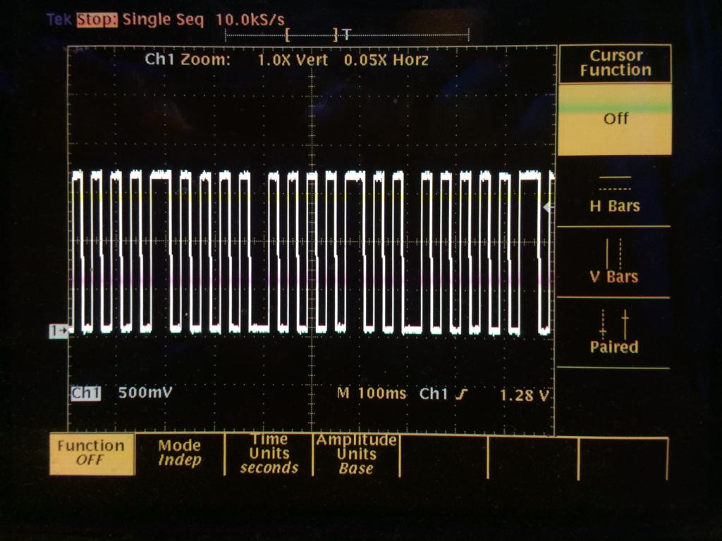
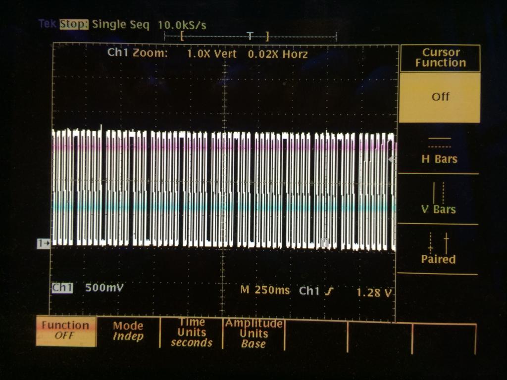
I have a device that pulses a signal to an IR LED to be recognized by a camera. The pattern of pulses can be selected from 0 to 255, i.e. you can have 256 individual trackable LED beacons. I've analyzed the LED pulse pattern for one of the beacons set to #0 and #255 using a digital oscilloscope. The patterns are below after being decoded from what I think is Manchester encoding. I can not figure out any pattern and wanted to know if anyone has any advice to figure this out. I don't want to have to analyze every single signal from 0-255 although I guess that is an option. The end goal is to be able to reproduce the LED signal using the propeller chip.
It appears that the bit pattern is 19 bits long, but its weird that its inverted on the first one but not the other. See the two attached images of the waveform for your reference. The long pulses are 40mS and the short pulses are 20mS.
Thanks,
Marcus


I have a device that pulses a signal to an IR LED to be recognized by a camera. The pattern of pulses can be selected from 0 to 255, i.e. you can have 256 individual trackable LED beacons. I've analyzed the LED pulse pattern for one of the beacons set to #0 and #255 using a digital oscilloscope. The patterns are below after being decoded from what I think is Manchester encoding. I can not figure out any pattern and wanted to know if anyone has any advice to figure this out. I don't want to have to analyze every single signal from 0-255 although I guess that is an option. The end goal is to be able to reproduce the LED signal using the propeller chip.
#0:    ...1111110000011111000...
#256:  ...00000010101010110001111110101010100111...

The ellipse (...) means the code repeats the pattern from there
It appears that the bit pattern is 19 bits long, but its weird that its inverted on the first one but not the other. See the two attached images of the waveform for your reference. The long pulses are 40mS and the short pulses are 20mS.
Thanks,
Marcus


Comments
Compare the results of encoding bit patterns than differ by only one bit, see if there's a pattern between the output
changes compared to the input bit difference.
For instance compare 0 to 1, 0 to 2, 0 to 4, 0 to 8, etc.
Unfortunately, there is no option to set the ID tracker to an ID of zero. Only 1 through 255.
Thanks,
Marcus
The data is a constant stream, there are no special "start" or "stop" patterns, so the data in that table could be rotated in either direction. Does that make sense?
Thanks,
Marcus
And it is read from left to right.
-Phil
the waveform you posted it looks very similar to when I am driving my panel. Good luck reverse engineering!
Why so cryptic?
1: what is the device
2: what brand is the camera
With that info, Googling may turn up IRDA encoding used etc
This is a good tip, I will try and decode the waveform using this method today.
1: ID Tags by coolux Media Systems, http://www.coolux.de/cooluxsupport/tech-blog/blog/detail/real-time-tracking-id-tags/
2: Prime 13 by Optitrack, https://www.naturalpoint.com/optitrack/products/prime-13/
Phil, your idea was spot on. I found the pattern using FM0 and it isn't complicated at all. Not even any checksum or error checking involved
Here is the updated spreadsheet with values for your enjoyment.
Thanks for everyone's help,
Marcus