Propeller System Module 3: Manta
Wanted to share progress and get any feedback anybody might have on development of what I'm currently calling PSM3.
Basically, it's a Propeller board that includes a 3.5" LCD touchscreen driven by SSD1921 image processor.
There are several cool things about the SSD1921, one of them is that it can capture video from a standard cmos camera.
I just today figured out how to get it to show video from the camera on the LCD screen.
Here's a photo of the screen with the camera (on other side) looking at flowers:
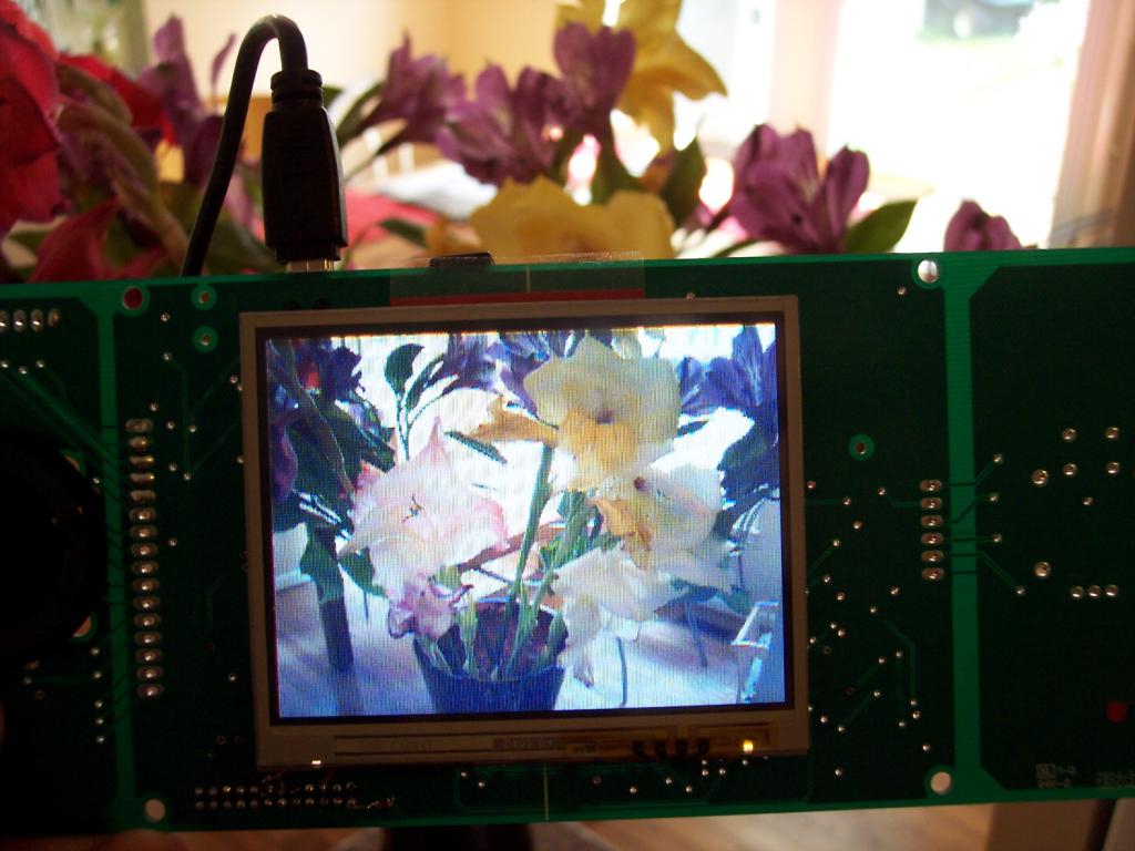
Very happy to get this working because the digital video interface was my main reason for picking SSD1921 for this.
Both the SSD1921 and cmos camera modules are very sparsely documented, so it's been a lot of trial and error to make this work...
Also, there aren't very many (if any) code examples for SSD1921.
But, all that trouble seems worth it now that I can capture images and video from the camera.
My next software challenge (that I might put off for a while) is to figure out how to use the SD card interface.
Once we have that, the SSD1921 can save/load jpg images directly from SD with 4-bit (fast) interface.
I'm toying with the idea of adding goodies on the sides of PSM3 to form possibly detachable wings.
Right now, I have a 7-way tactile switch with jog, nav and select on one side and an analog joystick on the other.
Here's photos of the current PCB:
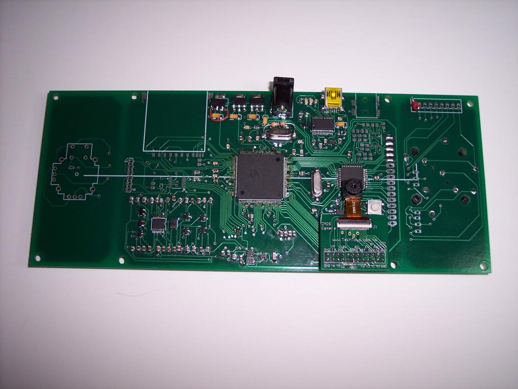
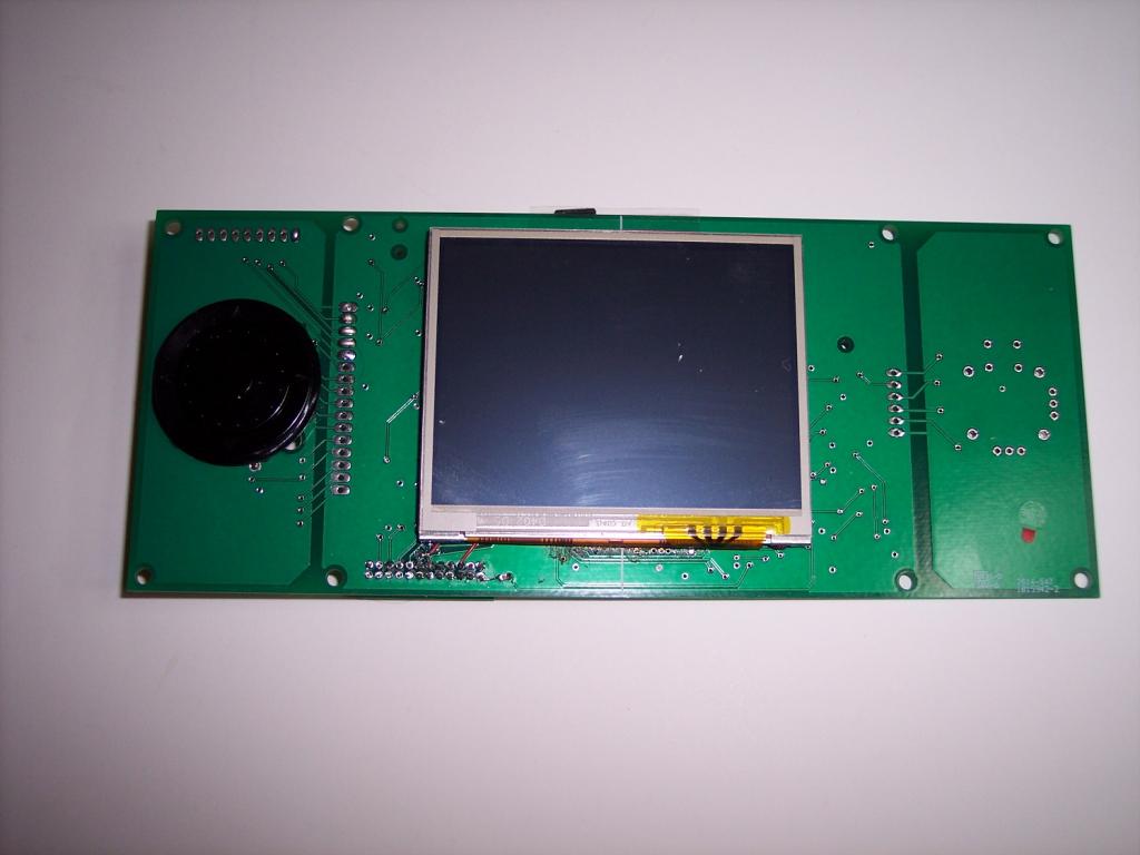
There are other things I'm contemplating adding to the wings, such as RTC, NTSC video out, uSD, sram, xbee port, 9DOF mems, etc.
But, I have to weigh this against it costing a fortune and taking forever to make...
Update:
New PCBs have all the extras (except sram) and reduced width (post #19):
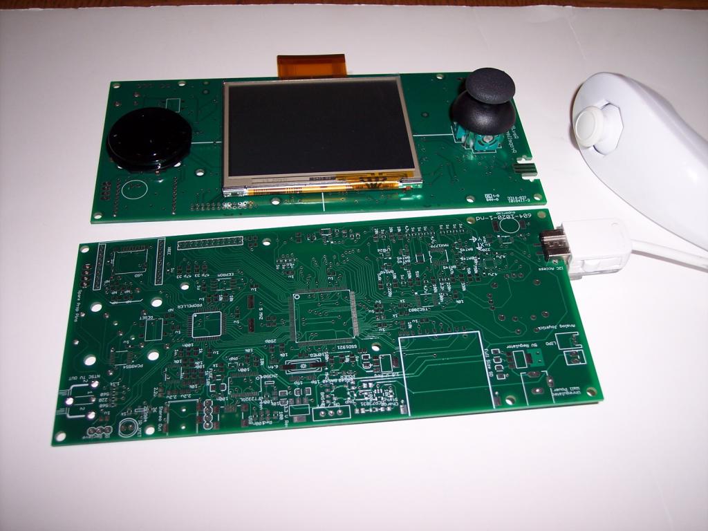
Update 12Dec14: Latest prototype appears to be 100% functional (see post#31)! May be done with the hardware design part of this project.
Update 20Feb15: Hardware side of this project is finally done! Lots of work needed on the software side though... Here's a photo of the final board:
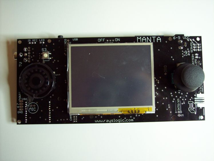
Update 02Mar15: Manta Product Brief now posted online: http://www.rayslogic.com/Propeller/Products/Manta/Manta_ProductBrief.pdf
Basically, it's a Propeller board that includes a 3.5" LCD touchscreen driven by SSD1921 image processor.
There are several cool things about the SSD1921, one of them is that it can capture video from a standard cmos camera.
I just today figured out how to get it to show video from the camera on the LCD screen.
Here's a photo of the screen with the camera (on other side) looking at flowers:

Very happy to get this working because the digital video interface was my main reason for picking SSD1921 for this.
Both the SSD1921 and cmos camera modules are very sparsely documented, so it's been a lot of trial and error to make this work...
Also, there aren't very many (if any) code examples for SSD1921.
But, all that trouble seems worth it now that I can capture images and video from the camera.
My next software challenge (that I might put off for a while) is to figure out how to use the SD card interface.
Once we have that, the SSD1921 can save/load jpg images directly from SD with 4-bit (fast) interface.
I'm toying with the idea of adding goodies on the sides of PSM3 to form possibly detachable wings.
Right now, I have a 7-way tactile switch with jog, nav and select on one side and an analog joystick on the other.
Here's photos of the current PCB:


There are other things I'm contemplating adding to the wings, such as RTC, NTSC video out, uSD, sram, xbee port, 9DOF mems, etc.
But, I have to weigh this against it costing a fortune and taking forever to make...
Update:
New PCBs have all the extras (except sram) and reduced width (post #19):

Update 12Dec14: Latest prototype appears to be 100% functional (see post#31)! May be done with the hardware design part of this project.
Update 20Feb15: Hardware side of this project is finally done! Lots of work needed on the software side though... Here's a photo of the final board:

Update 02Mar15: Manta Product Brief now posted online: http://www.rayslogic.com/Propeller/Products/Manta/Manta_ProductBrief.pdf


Comments
http://forums.parallax.com/showthread.php/150336
What I'd really love to do is replace SSD1921+Prop1 with a Prop2 chip.
Prop2 should be perfect for this and be much more powerful.
Current feature set:
3.5" TFT LCD touchscreen
2.0 MP camera
analog joystick
7-way tactile switch with jog
full size sd card with 4-bit interface to SSD1921
usd card with 1-bit prop interface
9DOF mems with gyro, accel, magnetometer
Lipo charger and power with USB or unregulated wall power
USB programming
stereo audio out
TV ntsc output
IR transmitter and receiver
RTC with supercap backup
Nunchuck interface
battery voltage monitor
xbee interface
2 free pins!
I was going to make the sides detachable, but decided against that.
Could still make a "core" board, smaller and without all the extras...
But, I think a 4.3" or 5" LCD board would be better for that...
This 3.5" screen is perfect for a portable, battery powered system.
Putting it all on one board also means it can fit in a thin enclosure...
BTW: I've got some very cool things to try with the SSD1921. One of them is simultaneous LCD and TV out showing the same thing...
The SSD1921 has an 8-bit mode with CLUT. I think I can load that up and then transfer TV screen pixels directly to SSD1921.
The SSD1921 also supports screen stretching so it will scale the TV resolution to fill the screen.
Another trick I want to try is camera out to TV. The SSD1921 supports YUV mode. Maybe I could somehow manipulate the bits to be what is needed for the Prop NTSC driver...
Remember something about only needing DI and DO to be hooked to Prop pins to make it work...
Hope that's right...
Another trick I want to try is replacing the camera with an NTSC video decoder.
I think something like the TVP5151 should be fairly easy to use instead of a camera.
Then, you could hook up a regular NTSC output camera with a long cable...
You can save an up to 2.0 MP image as a .jpg file on SD which you can then read from with the Prop.
Or, you can not save to SD and just stream out to Prop from SSD1921 ram.
I think Beau has a high-speed Prop-Prop link using only 1 or 2 Prop pins.
That might be the fastest way to send over the picture.
Or, you could just use fullduplexserial with 2 pins and as high a bitrate as you can...
So, yes, assuming Pink or Spinneret have 2 free Prop pins, that would work.
You could have a fairly live web cam that way...
OR... I could pay now so I don't have to worry?
You are correct about the xbees only needing DI and DO. But if you intend on powering this with a battery I'd strongly recommend using the sleep pin as well.
You can't put it to sleep over DI/DO ? If not, I think you're right, you're going to want to put it to sleep under battery power...
Does this look right?
Here's a big screenshot of the current board layout and the schematics:
PSS: The Eagle schematic print to pdf leaves something to be desired... I see it cut off a lot of stuff...
This one's a little better:
SSD1921_Test9a.pdf
The 7-way tactile switch and joystick now plug in properly.
The Nunchuck connector actually works (mechanically at least) and locks in the Nunchuck.
If everything works, this could be the last prototype before production:
I can copy over an 8-bpp screen dump of NTSC TV video pixels (from here: http://forums.parallax.com/showthread.php/95283) to SSD1921 RAM.
Then, use the accelerated 2D stretchblt function to copy over that buffer to the 16bpp LCD screen buffer while at the same time using the CLUT to translate
TV colors to RGB. Screenshot of result:
This was just a static image, but I think I can do the same thing with real-time Prop TV output.
This would allow simultaneous display on LCD and TV of exactly the same image...
Turns out my LDO was not "low" enough and my p-channel FETS were too resistive. But, was able to buy better parts and now it's all good.
Can now power by USB, barrel jack or LIPO battery with seamless transition and charge the battery at the same time via USB or barrel jack.
I'm very happy with the way the power circuit is working at the moment.
Also tried out the trick of simultaneous TV Text display on TFT and RCA jack output to real TV. Got it working but needs some work to increase TFT update speed.
It's only 1 or 2 times a second now. But, in the future, it should be possible to use the VGA video circuitry of the propeller to dramatically increase update rate.
The Wii Nunchuck jack also works. It's trouble if you plug it in upside down though because it shorts out power...
I'm also thinking about how to do game type graphics... It appears easy to do at some lower resolution and then stretch-blitting to full screen.
But, for higher resolution, seems I need to figure out how to sync with vertical unblanking. The 2D accelerated functions should allow nice graphics to be generated during vertical blanking. May need to increase the vertical blanking time.
Also, I have some of the newer camera modules from techtoys.com.hk and want to get those working.
Really nice work.
Would there any way to get two modules that haven't been cut apart? For stereo camera work?
It looks like it might work. See here for a video of it working: [video=youtube_share;snfeXGSdbF4]
This is really basic, clearing the screen and then drawing a few blocks and an ellipse.
But, this was mostly spin. If pushed to assembly, should be able to do more...
As for stereo, it'd probably be better with 2 of these systems. But, these are big boards.
If there was some demand, I could think about a smaller, 1" or 2" system using SSD1928.
Moves some spites around using bitblt and transparent blit
I've completed the assembly driver and the pac-man type demo runs much faster now.
It's very clear now that drawing during vertical refresh is possible and I'll work on some better demos of that soon.
Just finished "TV_Text_Demo" for PSM3. This gives pretty identical functionality as TV_Text, but on the TFT screen.
Trick I'm using here is embedding the 8x16 font as a 1bpp .bmp image in the Propeller (takes up 4kB),
Then, upload font to free space in SSD1921. Then, I do 2D accelerated stretchblit to copy 1bpp characters to
the 16bpp screen buffer. Have to use stretchblit for this even though not actually stretching, just converting from 1bpp to 16bpp.
This is actually a very powerful function. Anyway, here's what it looks like (there are 2 more rows than the real TV_Text_Demo):
At the moment, it uses more than the 2.8kB of the original, mostly due to embedded font.
But later, once the SSD1921 direct interface to SD is working, we'll be able to load the font from the full size SD using SSD1921 operations
with much lower overhead.
Next up (now that I can display text easily) is test out all the i2c functions.
There are a lot of them... joystick, pad, rtc, accelerometer, gyro, compass, etc..
The 2D graphics engine is a lot like having a 9th cog there with direct access to the video RAM.
The camera interface is maybe like a 10th cog with direct access to video RAM and camera interface.
And, there's the SD interface, which can act like an 11th cog, doing things that I'd normally use FSRW to do,
but doing them faster.
BTW: Forgot to mention that I did test out the IR transmitter and receiver and they work with Beau's code.
So, a learning super-remote control is on the horizon...
Just populated the latest prototype PCB and everything is working (without jumper wires this time)...
Also, I've got FSRW working with the 4-bit full-size SD card connected directly to the SSD1921. I think this will be great for moving images directly from SD to screen buffer, with option of jpeg encode/decode in between.
Camera port works, touchscreen, jog dial and joystick work. RTC works. 9DOF mems works. Power works via jack or USB.
Still need to test a few extraneous things like TV output, IR transmit/receive, Xbee port, nunchuck port, lipo charger, etc.
Testing is actually a problem for this big board... Many things to test...
But, once that's done and I touch up some silkscreen, I'm ready to place the order for production boards.
BTW: I think I've decided on "Manta" as the codename for this board.
I also need to pick a soldermask color. I've always done green in the past, but this time thinking about blue or white or black...
Here are photos of what I think is the final prototype: