

Fried BS2
 alnajjar1
Posts: 110
alnajjar1
Posts: 110
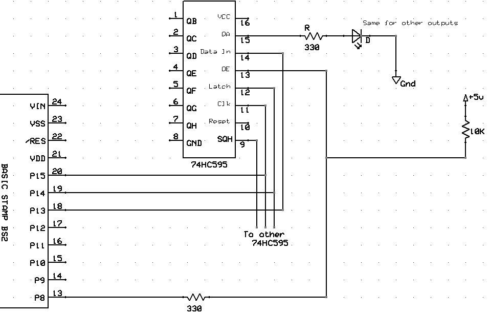
I use the BS2 with 74HC595 regularly and my circuits works flawlessly over years. Last week, I had a BS2 that died completely and not sure why - nothing has changed. However, both the 595 and the BS2 are not working. I am attaching the circuit in case someone can spot some potential hazard with my design (it is really not mine - it is straight from the Parallax manual).
http://forums.parallax.com/attachment.php?attachmentid=109577&d=1405118308&thumb=1&stc=1
Do I need resistors between the BS2 and 595? Is there a robust way to 'isolate' the stamp for industrial type applications (like my Museum where repeated use, vibration and dust are common issues).
Many thanks
Al
956 x 611 - 72K
Comments
Normally a failure such as yours would be attributed to a power supply going bad.
What is supplying the power to your board?
EDIT: Chris beat me by a minute.
I typically use a 13.6VDC - 19A Radio Shack supply. It is very stable and reliable. I also use the Supercarrier board from Parallax which is perfect for my projects. One issue might be that I am using the 5VDC supply from the Supercarrier to feed the 595 ICs which I have a total of 9 to drive 72 LEDs. Would that be an issue? The LEDs use the power source directly and not from the supercarrier.
Al
How? may I ask?
circuit.bmp
thanks
Is that exactly how you have it?
'595 pin 16 (Vcc) goes to +5 ?
13V "Gnd" goes to super-carrier Gnd (Vss) ?
The pushbutton part of the schematic is missing a 10k on +5 side but it is on the circuit.
Sorry about that.
Al
So, does the supercarrier's on-board LED still go on?
Any "quality time" with the voltmeter?
If you disconnect all of the external circuitry from the supercarrier, what then?
"19A" Radio Shack supply?
Is that a "regulated" output or is it just a B.A. transformer with a rectifier and a B.A. cap?
What's the output of that guy with no load?
The supply is regulated (as far as I can tell). The voltage is stable within 0.01V. When SC and other circuits power, voltage on the supply is steady at 13.6VD with no appreciable drop or fluctuation even if loads are turned on. I tried turning 3 of the LED strips (roughly 1A), and voltage is steady at the supply.
With a robust regulator at the SC, how would the main supply fry the stamp or the 595?
I have had a router failure from such, so I changed over to a small industrial switcher supply that has much more protection that a cheaper device. Haven't had any problems since I changed.
Did your power supply fail completely as well?
+++++++++++
If the 595 failed, it might have just damaged the i/o pins connected to the BS2.
Are other i/o pins able to work or is the BS2 completely gone?
So, you're saying that the Vdd/VR1 supply is still good (according to Mr. Voltmeter)?
You could try replacing the EEPROM as a DIY repair, but that may not be successful.
It still means you have a dead BS2. If it completely shuts you out and it doesn't remember its previous program, it is gone.
How did you decide the 595 was also damaged? Is this a MOSfet device or not? I believe 74HC595 is CMOS and that too is more sensitive to the kind of electricity that lightning will provide.
Protection from lightning can help, but nothing will ever be 100% failsafe. If you get a lightning strike on your front door step, even protected devices can't be saved. You could go to battery operation to completely isolate the power from spikes on the transmission lines, but that means managing battery charging and more.
What was the weather doing at the time it failed?
Thanks for your help.
Al
A better schematic showing all VIN, VDD, and VSS conections.
Better yet a clear picture of your setup. That works out better most times.
Thanks again,
Al
And a power supply that actually has a formal power line transient suppresion ciruit (for repeat events, not one-shot) would be another plus.
Something like this... (the come in many more amps if you need more) Be sure to get the 120VAC version and not a 240VAC only.
http://www.ebay.com/itm/DC-12V-3A-36W-Switch-Power-Supply-Driver-For-LED-Strip-Light-Display-SS-7-/170800232981?pt=LH_DefaultDomain_0&hash=item27c47cba15
It sounds as if you are using an automotive battery charger from Radio Shack as your supply now. Lead Acid cells don't need any transient protection, so such a charger is unlikely to provide any.
@everyone
Apologies for interrupting the postmortem, but the OP seem to want an idea of why the failure was out of the blue and selective.
If somebody chooses to believe some possibility or other then that's another matter.
Context is a significant part of the information.
A. It ran fine for a long time. (Tends to indicate that the wiring is adequate to the task and design.)
B. Florida is home to a lot of thunderstorms throughout the year.
C. It seems that no extra measures were taken to protect from power line spikes migrating into project.
D. The device may have been hit several times over the life of its use and finally succumbed.
I am not sure that you would every find out exactly 'why' the failure occurred unless you open up the chips in question and examine them under magnification. More magnification that I have or can afford.
When the probabilities are in favor of certain possibilities, and absolute certainly is a costly waste of effort.. try to accept what is apparent.
This is not so much about be guilibe and blindly believing as it is about being pragmatic.
Chris is correct that an oscilloscope might offer much better diagonostic information. I am not even sure if my multimeter is very accurate as I have never had a reference to calibrate it against.
Using something like this +++> http://www.radioshack.com/product/index.jsp?productId=2103960
may be handy, but is not really a long-term optimal design.
Loopy,
This statement travels a slippery slope. I used to work for a Fortune 500 Company that built Fiber-Optic amplifiers that cost about 100K+ each. Inside were some laser assemblies that were failing in less than 10 years which should not have been happening. I won't get into the details but suffice it to say considering the cost of these laser pumps (as they were called) the manufacturer had them analyzed under and electron microscope to see what caused the failures. Not going to get into the details, again, long story short. $5,000.00 laser assemblies that were supposed to operate for 30 years were failing prematurely and not because of of anything in the circuit design or running outside of spec.
Post hoc ergo propter hoc.
You just gotta believe!
Is there a life-time warranty I missed, or a 20,000 hour mean time to failure that was not achived?
I just noticed that he shared a common problem with me in Taiwan -- frequent lightning. So I suggested he clean up in power supply and not expect anything to be a perfect solution. When you deal with thousand of volts and thousands of watts attacking something left on 24/7; you have to accept occasional failure in spite of protective measures.
BS2 and all Parallax products have a simple 30 day warranty and are neither extremely expensive or key infrastructure devices. So opening up chips and finding the source of failure seems unlikely to happen.
If you look at the voltage regulator pin out, the Vin, Vout, and GND are close enough together that if the device blocks a lightning strike, the pinout may just cause 10,000 volts to jump and reach components downstream, such as the EEPROM or the 74HC595.
It is nearly impossible to prove anything. But these are plausible factors to consider. PJ seems to want absolute proof.
No, I just don't agree with the conclusion to which you jumped, absent any evidence.
Fair enough. I just didn't realize that providing evidence to your standards was so important.
Anytime someone is using a 13.5-13.8VDC 19amp power supply, it just seems obvious the device is primarily designed to work as a stand-in and/or trickle charger for large lead acid batteries.
I did try to locate it at Radio Shack's on-line catalog and came up the link provided. It says it is 15 amps in the header, but the detail says it is or was 19amps at one time. And of course, it is a black box without any internal documentation as to how it provides power.
Seemed enough to me to suggest that an industrial grade switcher with good line protection was appropriate... especially in South Florida.
Demanding the OP revise his schematic to meet your standards seemed to be counter-productive. And I have observed a lot of old PIC designs for CNC stepper control seemed to get their EEPROMs wiped out by transients in actual use.
Why be so hard-nosed about proof and evidence? The devices need replacement, and the power supply should likely be upgraded.
If would be more helpful if you revised the errors and omissions in his schematic or made additional suggestions rather than just demand the mode of communication always fits your expectations.