Facial Recognition Board for PropCam-DB
 william chan
Posts: 1,326
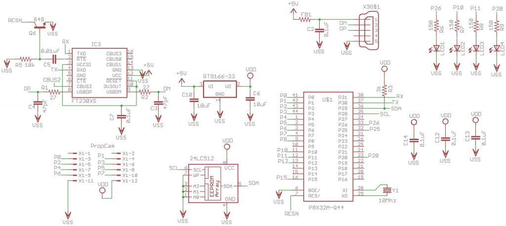
This board is supposed to plug directly into PropCam-DB and light up your face with 4 white LEDs.
It is exactly the same size as the PropCam-DB board.
The 3mm LEDs squeeze through the 4 mounting holes on the PropCam-DB board.
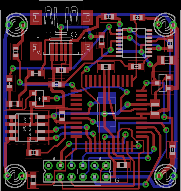
Finally managed to squeeze all the "required" components in.
After taking your face photo, it is supposed to send the BMP image to a mini PC to do the recognition crunching.
The pcb layout does look a bit tight does it?
Does the USB connector chasiss need to be connected to VSS?
If you find anything wrong with the circuit or layout, please let me know.
Thanks.


Comments
-Phil
Can I connect RTS directly to Prop Reset pin to eliminate the transistor-capacitor-resistor circuit?
Will Propeller Tool still be able to program the Prop chip? ( via the USB connection )
USB cable will always be plugged in during operation. ( as Propeller chip runs on USB power )
-Phil
I'll repeat some of the advice I've read which I think applies to your board.
I've read it's good to keep the traces between the Prop's Vss pins and the traces between the Prop's Vdd pins as short as possible. The Vss pin next to P31 looks has a very long trace between it and the other Vss pins. I think this trace may be long enough to possibly cause a problem.
Is your board going to have a copper pour? I've read they're a very good idea (I think I learned this from Phil). It looks like there may be room on the bottom of the board for a fair amount of copper but I'm not sure how much a copper pour would help on the top. With a copper pour connected to ground, you could probably reduce the distances between the Vss pins.
Several Propeller board designs I've seen use a copper pour on both the top and the bottom of the board. The top pour is connected to Vdd and the bottom pour is connected to Vss. This is how jazzed designed his TetraProp and I believe the Propeller Proto Board uses a Vdd plane under the Propeller chip on the top side of the PCB and a ground plane on the bottom of the PCB.
I've read 90 degree turns on a PCB trace are not desirable. Apparently they can cause issues with high speed transmission and I've read they can cause issues when the board is etched (though I'm not convinced of this one). I've also read 90 turns look ugly. Most of the PCB designs I admire have nice 45 degree turns in their traces.
I've read it's a good idea to have traces running left and right on a single side of the PCB and traces running up and down on the other side of the PCB. I've found this bit of advice to be a huge help when laying out a cramped board.
I've also read it's not a good idea to have traces running close to the edge of the PCB. Some of the traces on your board seem closer to the edge than many would consider safe.
It might be because I use inexpensive fab houses but some of the traces look like they come too close to other components. The 3.3V line sure looks like it passes too close for comfort to the 5V pad of the voltage regulator. There are several other traces which pass closer to pads than I'd be comfortable with. It might be these traces are fine and this is just my worrying about obeying the design rules of the inexpensive fab houses. Have you run a design rules check? Again, this might not be an issue with the fab house you're using.
The vias on your board seem to be a bit larger than I'd expect on a cramped board. Can the size of these be reduced? (I'm not sure about this and doubt the vias need to be reduced in size.)
Without mounting holes, I assume the board will likely be mounted using double sided tape. It sure seems like that crystal on the back side of the board will be in the way when trying to mount the board. I'm not sure how hard it would be, but I it looks like there's room on the right side of the Propeller for the crystal or oscillator you're using. What about rotating the Prop 180 degrees and moving the crystal to the top of the board? I'm not sure, but I think it's very likely that using one side for horizontal traces and the other for vertical traces that their would be room to have all the components on the top side of the PCB. I'd think having a clean back surface would be a big help when mounting the board.
If you have a Propeller Backpack, you ought to study how Phil laid it out. IMO, it's very well done and looks great. There are several, very nicely designed, small Propeller PCBs on the Smorgasboard. I often look at the boards on the Smorgasboard for ideas on how to best layout a board.
Thanks for your many comments.
I rotated the Propeller chip 90 degrees and now there is less vias. ( see new layout image ).
I also reduced the via hole size to 0.5mm.
I am still scared to do copper pour, so will leave it out for this project.
A plastic case will be printed using a 3D printer, so mounting will not be a problem.
Thanks again.
Now the hard part, making it work...
That turned out very nice! 'Can't wait to see what you do with it!
-Phil
Currently the Propeller can be programmed by PropTool via the USB connection and runs well at 80Mhz. It can communicate with Parallax Serial Terminal program at 115200 baud.
Unfortunately I am unable to aquire any images yet. The same test program works when using Propeller Backpack.
Can I confirm with you the following :-
a. Only 3.3v supply is required for PropCAM. 5v supply is not required.
b. Only propeller pins P0 to P7 are required to connect to PropCam.
How to detect whether
cam.acquire(grab)
succeeds or fails?
+3,3V, Gnd, P0-P7 are all that are required (unless you plug something into the mezzanine socket that needs +5V).
Don't forget that the Backpack uses a 10 MHz crystal and that the demo programs written for it specify 10MHz and PLLx8. If your board differs from that, you'll have to modify the CON section.
Also, I notice that your board does not have pull-ups on P4..P7 like the Backpack does, so you will have to add a wire jumper or header-and-shunt to the PropCAM across the Vdd-SDPU header. This will pull the sensor's SDA line up to Vdd via the onboard 4.7K resistor.
-Phil
Good advice on this issue; I can identify with this, ran into it myself. You do not want long traces, because can act like an antenna, emitting data packets onto you board. Long traces
also add "load" to the drivers, and they are designed with a fanout load expectation, represented by a capacitor load, in some designs. having alot of square traces in parallel could
act like a SAW(Surface Acustic Wave) filter, commonly used on radio TX/RX boards. Board looks good!
Amazing!
-Phil
I looked thru your spinneret bmp demo code but it seems to be too complex for my brain.
The HTPP header and BMP header seems to be mixed together in one function.
I would be most grateful if you could show me simpler code which sends only the BMP header and image data via the fullduplexserial tx() function.
That surely is a thing of beauty!
Great work William :-)
After removing the HTTP header, I got 26 bytes for the BMP file header which I think should be correct now.