Shop OBEX P1 Docs P2 Docs Learn Events
Thermistor code help — Parallax Forums

Thermistor code help

Mike2545Mike2545 Posts: 433
edited 2013-07-05 12:50 in BASIC Stamp
Hi guys, I am building a greenhouse and a vent control system to automatically control the vents. I want to use a thermistor because of the rugged nature of the probes. I got this one HONEYWELL 535-59DV26-303 THERMISTOR ( http://www.mouser.com/ds/2/187/009035-1-EN-20984.pdf ). I am having trouble with the RCTIME portion of the code to get a temperature reading. This system does not have to be pin point accurate but should be +- 2°F

Any help would be appreciated.
997 x 498 - 38K

Comments

  • Mike GreenMike Green Posts: 23,101
    edited 2013-07-04 11:52
    Have you looked at the chapter on the RCTIME statement in the "Basic Stamp Syntax and Reference Manual"? It has some discussion of how to use it to measure resistance like that of a thermistor. Also look here for more discussion. Remember that a thermistor has a quite wide range of resistance. You may need to set up a spreadsheet with a graph to show the range of values returned by RCTIME vs. temperature for different capacitor values. You may also need a series resistor and/or a resistor in parallel with the thermistor to get a more useful temperature range. Set up your spreadsheet with these and experiment. Note that you can use either a byte variable or word variable with RCTIME. You'll want a word variable to get a wider range of values.
  • Mike2545Mike2545 Posts: 433
    edited 2013-07-04 12:16
    Thanks for the reply Mike, I was just wondering if someone had done the code for an NTC thermistor output and a schematic to help me understand.
  • Mike GreenMike Green Posts: 23,101
    edited 2013-07-04 13:06
    Again, read the Manual's chapter on RCTIME and the EMESystems webpage. Use the formulas for series and parallel resistors (Rs = R1 + R2 and Rp = 1/(1/R1 + 1/R2)) to see what the effect of different resistors might be in coming up with a total resistance value to substitute in the RCTIME equations. If R1 is the thermistor and R2 is the series or parallel resistance, you can easily make a spreadsheet. The details of the best values depends on the thermistor and the temperature range you're interested in and will vary all over the place.
  • Mike2545Mike2545 Posts: 433
    edited 2013-07-04 13:15
    Again, thank you for your response, I had already perused most of that material, and did not want "to re-invent the wheel " -so to speak- I was interested to see if anyone had a block of code pertaining to that particular sensor...I will wait to see if anyone else responds, but it looks like I am on my own.
  • Mike GreenMike Green Posts: 23,101
    edited 2013-07-04 13:35
    It's not just which thermistor you have, but what range you want to cover and with what precision. The resistors and the exact formulas you'd need would depend on all of that and the likelihood of finding someone with the same application as well as the same thermistor is pretty slim. As always, we're also interested in giving people the information they need to learn to refine and maintain their systems, not just to put something together without understanding it.
  • Mike GreenMike Green Posts: 23,101
    edited 2013-07-04 15:25
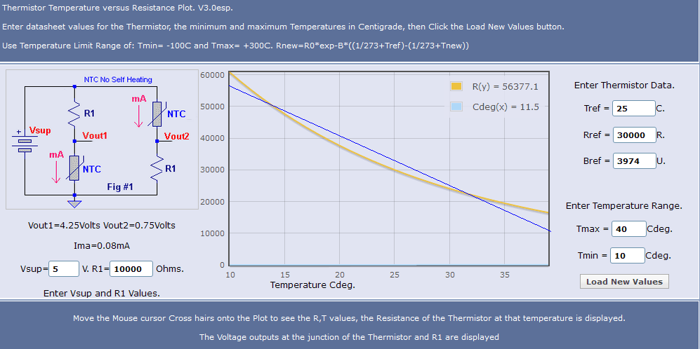
    Here's an example of the kind of spreadsheet I mean. It follows the schematic and formulas in the RCTIME chapter in the Manual. There's a resistor in parallel with the thermistor and the series resistor shown in the schematic. You can make the parallel resistor essentially infinite if you want to ignore it (like 10000000). Similarly, you can make the series resistor zero if you want to ignore it. I copied the thermistor values from the chart you posted in your first message.

    I get what look like reasonable values for a wide temperature range (10C to 40C) with a parallel resistor of 50K and a capacitor of 1uF. Next step would be to make up a test circuit and determine the raw RCTIME values for specific temperatures, then try to fit an equation to the data values (TC = f(RCTIME)). If you get enough data points, you could use table lookup with linear interpolation or, if you get a good fit, you can just use the equation you find to convert the raw RCTIME values to temperature.
  • Mike2545Mike2545 Posts: 433
    edited 2013-07-05 07:29
    Here are the readings I got. It is pretty much a straight line, I think that I could extrapolate the rest of the values based on these readings. Now to write the code...
  • Tracy AllenTracy Allen Posts: 6,662
    edited 2013-07-05 10:19
    I'd hesitate to use RCtime for that, especially when you want accuracy over a relatively narrow range of temperatures like 20°C to 35°C. . The threshold of the BASIC stamp will drift a bit with time and temperature, and the capacitor too needs to be stable. To evaluate those effects, put the thermistor in a constant temperature and direct a hair dryer at the Stamp end of the circuit.

    I'd prefer to use an ADC, because then the accuracy is better controlled by a stable reference resistor, Rref.
    thermistor_divider.png

    I'm attaching a spreadsheet that computes the values for Stamp DATA statements given the above circuit, given values for Rref, Vref, and points of the curve of Rt vs temperature. The Vref would drop out if you use a ratiometric converter. This is for a Davis 7818 soil temperature probe and covers quite a wide temperature range at 9 °F increments. Also a Stamp program that uses the DATA statements, and it interpolates for values within each 9°F interval.
  • Mike2545Mike2545 Posts: 433
    edited 2013-07-05 12:50
    Blow dryer test : windy and hot with a chance of data drift...Thanks for the input Tracy.

    The test with the blow-dryer yielded small variations in the readings when directed at the capacitor (40° C) and nothing when directed at the Basic Stamp (aka PIC 18F1320).

    I'll work out the code and post it along with the circuit diagram when I get it all going....
Sign In or Register to comment.