

Audio mixing circuit

Hello,
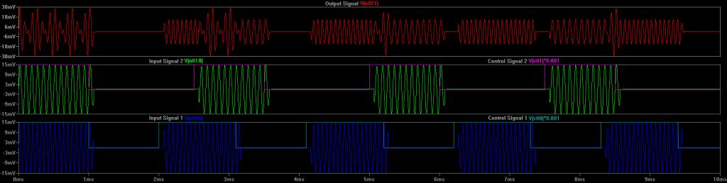
I am experimenting with LTSpice and my own circuit design, and I would like to get some feedback. I attached a schematic of a circuit that I designed using some basic op amps and a 4066 CMOS switch. The purpose of the circuit is to switch on and off a differential audio signal and pass it to a summer. I plan to connect many of these together to have the ability to turn on and off any of the incoming audio signals and have the summation of all of them at the output. Running a simulation seems to tell me that the circuit is working as expected. If anyone has any feedback for ways I could improve the circuit, or even suggest a completely different approach would be greatly appreciated.
Thanks,
Marcus
2ch Summer inverting 2.21.13c.pdf

1024 x 258 - 41K
Comments
Why have two resistors connected to the switch, one on input, one on output - these can be combined into one. You have an opamp stage
between each switch and the summing amp - no need, summing junction will work happily direct from the switches.
You will have cracks/pops on switching since at the moment of switching the signal isn't necessarily zero - to switch softly you
need to be more sophisticated and attentuate the signal gradually (there's probably a chip that can do that, but your idea
with the RC network isn't going to hack I don't think - I wouldn't expect it to because of buffered logic input stages (check it on a breadboard at least).
The CD4066 itself has mediocre performance compared to modern analog switch chips, a modern version will have only a few
ohms on-resistance and better linearity - there might be one with soft audio switching even!
You make a good point regarding the 4066. I was thinking it would behave like the 4016, which does not have the buffered logic. I have tried simulating countless circuits using P-channel JFETs but have had no luck. The many sophisticated audio switching chips that I have found seem to have too many additional features and are too expensive. I really only need a very simple audio mute circuit to quickly (100-200mS) fade the audio so there are no pops/clicks.
I plan to have 24 input signals each with it's one mute circuit, so I am trying to keep component counts down and cost low.
If anyone has any suggestions, I would greatly appreciate it.
Thanks,
http://www.intersil.com/content/dam/Intersil/documents/fn31/fn3116.pdf
Parts of this type, and this one in particular I've used.
...oops! Realized you were looking for a way to mute - sorry.
Dave,
Thanks for the suggestion, I have looked into these types of switches/multiplexers. But the problem with these is that the switch time is instantaneous, so there would be a possibility of hearing a "pop/click" sound when the switch turned on or off. This is not acceptable for my application. I would need a way to slowly switch (fade) the audio.
Thanks,
Marcus
http://www.pic101.com/audiosw/index.html
I'm currently using a variation of it.
be able to mute?
...yup. Commonly used are the LM13600/LM13700 devices. I've tinkered with them and they showed promise.
-Phil
Dear Dave,
Would you mind sharing your variation of the schematic and your component values? I have attempted simulating this circuit using LTSpice and have not had successful results. When simulating the circuit as described on that webpage, I get an output with a lot of DC component to the signal which I do not desire. See the attached schematic and image of my simulation.
This forum compresses the images I upload way too much, so a better version is on the second page of the attached PDF with the schematic.
Thanks,
Marcus
...sure - will do. It'll take a bit as my lab (and note access) is down for "house appraisal cleaning".
FYI - in the meantime (if you have the parts), build it and check the results against the Spice output.
though at $16 a pop, better really wanting that pro grade
http://www.ti.com/lit/ds/symlink/pga4311.pdf
8 channel, so only 3 of them needed. $14 a pop
http://www.cirrus.com/en/pubs/proDatasheet/CS3308_F1.pdf
6channel for $4 a pop
http://www.st.com/web/en/resource/technical/document/datasheet/CD00003197.pdf