

Encoder questions for electric wheel chair motors

Erco, if you clicked this you owe me $50.
I'm looking to add some hollow shaft encoders to some chair motors with the brakes removed. The shaft is 5/16 dia. and 1 1/4" long.
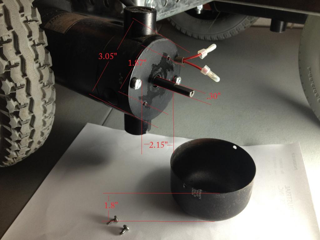 <- If you enlarge this you can see dimensions.
I found some nice hollow shaft quadrature optical encoders online for $60 each. They're probably a good deal but I don't want to spend $120 on encoders. EDIT: They're actually a really good deal. If I were to buy something it wouldn't be a hollow shaft, it would be a standard shaft encoder, then couple it with the motor's shaft. Doing so would drop the cost significantly.
With all the mounting options inside the end cap, I should make an encoder for it. I would like to do quadrature style optical encoders. I have looked at a lot online. Before I buy or make anything I thought I'd ask here because I've never worked with any encoders before.
Thanks for any advice you may have.
I'm looking to add some hollow shaft encoders to some chair motors with the brakes removed. The shaft is 5/16 dia. and 1 1/4" long.
I found some nice hollow shaft quadrature optical encoders online for $60 each. They're probably a good deal but I don't want to spend $120 on encoders. EDIT: They're actually a really good deal. If I were to buy something it wouldn't be a hollow shaft, it would be a standard shaft encoder, then couple it with the motor's shaft. Doing so would drop the cost significantly.
With all the mounting options inside the end cap, I should make an encoder for it. I would like to do quadrature style optical encoders. I have looked at a lot online. Before I buy or make anything I thought I'd ask here because I've never worked with any encoders before.
Thanks for any advice you may have.

1024 x 768 - 67K
Comments
My homemade wheel encoders worked quite well: http://forums.parallax.com/showthread.php?121179-Reading-Quadrature-Encoders&p=899765&viewfull=1#post899765
If you want to make a motor shaft encoder, that should be easy. Personally, I don't agree with conventional wisdom that you need a million PPR out of an encoder. That's useless resolution given backlash and slop. My guess is that you could paint that motor shaft half white/half black and that's all you need. Mount 2 sensors physically at 90 degrees and you're done. Any cheap optosensor could work. My favorite Hamamatsu P5587 ( http://www.junun.org/MarkIII/Info.jsp?item=48 ) is long gone, but you could use http://www.goldmine-elec-products.com/prodinfo.asp?number=G18740 ($1) or make your own out of 3mm IR LEDs & PTXs.
See also http://forums.parallax.com/showthread.php?109024-Scribbler-Wheel-Encoder-Project&highlight=scribbler+encoder
If you want an in-expensive option you can use the encoders from an old Microsoft mouse (Non optical). You should be able to drill out the wheel and glue it to the motor shaft. If you check at used computer stores, garage sales, and swap meets you can get those old mice really cheap. At least two encoders in each mouse. Sometimes a third if it has a scroll wheel but if you want to use that you'd probably need to get another identical mouse so you'll have a matched pair of sensors.
Robert
Excellent solution. You're absolutely right I think I was over complicating it. One 1/2 turn of that shaft moves the robot about 1/2" so that is more than enough. I'm going to get some white PVC with inside diameter of the shaft and make it half black. At this price I can build in some redundancy.
So those IR sensors work well with some LED illumination? I could put a diffused LED right next to each one. I think I'm going to make the IR pairs as well, but I couldn't resist ordering some of the ones you sent the link for.
Thanks Erco!
Thanks, I was about to use something along those line and pull the encoders out of roomba tires.
After reading Erco's post I don't think I need the resolution I thought I needed thanks to the low rpm gearbox on this thing.
I do have a lot to work with using these motors. I'm really glad I ended up with them, eBay with shipping for $150 including the tires and two sets of brushes. I pulled apart the gear box the there's no chance anything in there will ever go bad while I'm using it. Rock solid older Framco stuff.
Of course with a quad encoder's 2 sensors, you can measure rotation to 1/4 shaft turn (4 PPR) with a half black/half white shaft. You can always paint more stripes if you need more PPR.
And you could also make a slotted disk and use any number of optointerrupters:
http://www.goldmine-elec-products.com/products.asp?dept=1371
You may want to double check but I'm not sure if the Roomba uses a single channel encoder or a dual channel quadrature encoder. I prefer to use both channels for a full quadrature encoder.
Don't write off the mouse encoders until you've given them a shot. Here are some links:
http://hackaday.com/2008/05/16/how-to-scavenge-a-mouse-for-parts/
http://www.ing.unife.it/docenti/MarcelloBonfe/tsc/mouseHack.htm
The Roomba's motor encoders only have two wires from the sensor so I guess that is single channel.
I'm going to shove a piece of black PVC pipe over the shaft. I'm going to epoxy down lead tape lengthwise in half or quarters. I've noticed that metallic tape can bounce IR well in the dark compared to white paint and might not even need external light.
You may still need to paint the black PVC with flat black paint. IR penetrates and reflects off of various materials drastically different than visible light. I'm 99% sure you'll need to use an LED to illuminate the spot consistently. Typical optosensors provide an IR LED and IR phototransistor (PTX) in close proximity. You'll muck about with (rather, you'll empiricallly determine and experimentally ascertain) the series resistor values for the LED and PTX to yield the right high/low voltage divider values for your particular uC.
Too bad the Hamamatsu P5587 is discontinued. It was much more than a sensor. It was tiny and had lots of internal circuitry for filtering and Schmitt triggering.
That was a good part. Luckily it is pretty easy to add the triggering by using a 74HC14. Using a pair of those inverters cleans up the signal and works well. I've use them on the last couple robots that I needed to make custom encoders with good results.
I used some of those SparkFun boards on a Roboni-I robot erco made me buy.
erco's correct about IR just passing through some plasitics. I taped Al foil to a plasitic gear and hard drew encoder lines on top of the tape. The plasitic gear by itself wouldn't reflect the IR, it just passed right on through.
I disagree with erco about the need for a million ppr on encoders. Give a million any day. When I added encoders to my Mecanum wheeled robot, the lack of a high ppr encoder made the speed much harder to adjust. You might not need a lot of pulses to know how far you've gone, but lots of pulses sure help with speed control.
Duane: We can agree to disagree. We can decide not to decide. Can't we all just get along?
Resolution required certainly varies by robot and the application. I agree your nifty mecanum bot is the rare case where exact RPM matching is exceptionally critical. But in the more common case of a 2-motor differential drive robot, low res is fine for a motor shaft encoder in most instances. The S2 has incredible resolution based on its motor encoders, but not every robot needs that. Jon has a big beautiful motor shaft staring at him and an opportunity to simplify. I maintain that simply painting it half white/half black yields 2 PPR at the motor shaft, times whatever the gear ratio is (unknown, but likely 30 or more) yields 60 or more PPR at the wheels. That's plenty for measuring distance & turns and keeping the wheels in sync to drive straight from my experiments: http://www.youtube.com/watch?v=Trv682XZ_8c
Heck, 4 PPR is plenty good in some apps! http://www.youtube.com/watch?v=9l32qYXJfTg
Again, if there is significant backlash in the geartrain (or sideways wheel wobble in the case of the S2), you can't use incredible motor resolution anyway. IMHO, wheel encoders are better for odometry, which is where my interests lay.
@Jon: Please take a minute and describe your robot's drive system (wheels, motors & gear ratio), controller and its intended use. Why do you want encoders?
My MCU has two closed loop modes, one is speed, the other is position and you can even program in modifiers. Not sure if that helps because I still have not RT%M'd it http://www.robotshop.com/content/PDF/user-manual-mdc2250.pdf
Erco, my MCU is a Roboteq MDC2250. I completely agree about the shaft on these motors and I'm really glad they put brakes on them that can be easily removed. I don't think I could put them anywhere else on it.
[video=youtube_share;j_XR071igw4]
To get the gear ratio is that the number of time the shaft vs tire turns? I think that's going to be about
28:1
http://www.youtube.com/watch?v=mMru-ZA3yvQ
Here's a control system description. http://www.youtube.com/watch?v=VzbKlwc4GWs
Maybe I'll have to dust off Retrobot and git her around the Figure 8 challenge!
You might not have the space but its an idea
I mounted to the axle shaft I took of the seal cap an mounted the magnet in there
go to this post for more pictures
http://forums.parallax.com/showthread.php?138991-Telepresence-Robot-motor-mounts&p=1090879#post1090879
The motors are 24v and running on 12v. At low speeds if one tire runs over something small, like an extension cord it steers it off course. Since the diameter of the extension cord is so small, I think I will need good encoder resolution. Either way I'm going start with what we talked about doing before and then work from there. I don't mind having to change plans at all, if I need to increase the PPR.
I just rechecked the gear ratio is slightly closer to 29:1. So that means that the encoder will have 58 PPR.
Here's screen shot of the MC GUI. I love this thing but it's worthless in open loop mode...
I'm going to get the PVC and start messing around on Thursday. One thing I've been thinking about is not having to sink power to LEDs down there. Should I consider hall effect sensors and a couple magnets? I can drill a hole in the PVC and glue them in the holes then put the PVC over the shaft with a set screw to hold it tight. Also if I use two hall sensors side-by-side would that give me quadrature or will the sensors be too close together for them to know which one is changing first?
Thank you all very much for the help on this project.
It's funny I think i was typing the question as you were typing the answer. Do you see a benefit over using magnets combined will hall effect sensors over light?
Mine I built for under 25 10 bit but you can get 12 bit chips also, the magnet is the most expensive.
http://www.goldmine-elec-products.com/prodinfo.asp?number=G18740
I couldn't find a place that sells the boards. Do you remember how much it cost?
How are you reading it (which uC)?
My first AS5055 PCBs are due to arrive any day in the mail (hopefully tomorrow).
My bot also uses 24V motors at lower voltage (18/12V), but they have more gear reduction and spur gears, which is advantageous. If yours are worm gears, they tend to self-lock, which may come in handy for dynamic braking.
It's a tad weak at 12v at the lowest PWM that makes it move but it's also very slow and gentle. Which is nice until I get some sensors on it to stop it from doing damage. So far it has done damage inside my office so weak is good. Once I get the encoders on I'll be sure to have the sensors running by then.
You're right about the worm gears, and the wheels do not need brakes at all. I got some stuff to work on the encoders I hope to spend some time with it this evening. I have so many people asking to remote into the robot and drive it around now because of facebook lol. I can't wait to make it easier to drive.
Thanks again!
http://www.ebay.com/itm/260869973332
I picked up a set and they seem to work well.
At that price they're hard to pass up. Can you tell me the pin-outs? That would probably answer all of the other questions I have. Thanks!!
Ground
B
A
+5V
Robert
Hello Erco,
I've picked up a couple different styles but most seem to be 96Q128-40-00 which output 128 PPR.
Robert