Scratch Built Robot - In Progress
I'm going to go ahead and start a thread. I'm begining down the road I had always wanted to travel down since I was in HS. Building a robot. A few years ago I aquired a small Harbor Frieght milling machine mainly to drill PCB boards and later it dawned on me that I could make my own parts and make it just how I wanted. Since then I got further and further wound into the world of metalworking. I now have a really basic shop setup with a much larger mill and a 10" lathe, drill press, saws, ect. I finally made it back full circle to the idea of building a robot from the long 2 year CNC conversion on my mill. Only now I wanted to build mine up from scratch making as many of the parts as is practical for me to do.
The purpose behind the robot is to be a security sentury. I plan to have it roam the house at night or while away and use several sensors (PIR, glass break, ping, video) to look for possible intruders. Depending on how far I get I can have it alarm on the bot or maybe send a page/email. Otherwise its just a platform for me to learn seveal areas of interest. Mechanics, electronics, machine automation, programming. The plan is to use a Quickstart as the main brains, and perhaps some peripheral Arduino, PIC32, ect controllers to handle the mundain sensor and movement hardware. The rough specs are (and these are really fluid at present)
Power: LiPo 11.6V 2200mah batteries for drive (Tests show 3 hrs of constant on time / *much* more if steppers are powered down when idle ). Possibly NiMH batteries for electronics or maybe a second LiPo
Stepper based drive system: I have 2 NEMA17 motors with fairly high torque. Belts will gear down drive to keep torque up for running on 3 to 4" wheels.
- Drive is implemented on a Diligent UNO32 controller that will take I2C commands and run the steppers, manage power and monitor battery voltage.
Ultrasonic Distance Sensors: To manage deciding the most open path ahead and perhaps watch for objects that are moving in patrol mode.
PIR Sensor: Periodic pauses to perform a motion detection check in patrol mode.
IR Prox Detectors: For non-contact obsticle detection.
Bump Switches: For last ditch avoidance.
Floor Feelers: So an open basement door doesn't spell an early doom.
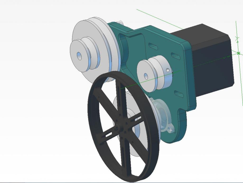
I am currently building the drive system. The UNO32 and the Prop are communicating over I2C at 400KHz and the command system is mostly working now. As is the battery monitor that prevents over discharge of the battery by shutting down the stepper drives when it drops under 10V. Mechanical parts are starting to be made. I have made a set of pulleys for one side and will soon be making the bracket, shafts, and bearing blocks needed to test it out. The calculators I have seen suggest I have enough torque to move an 8lb robot on level ground and that should be well over the real weight.
Here's some photos of what I have so far.
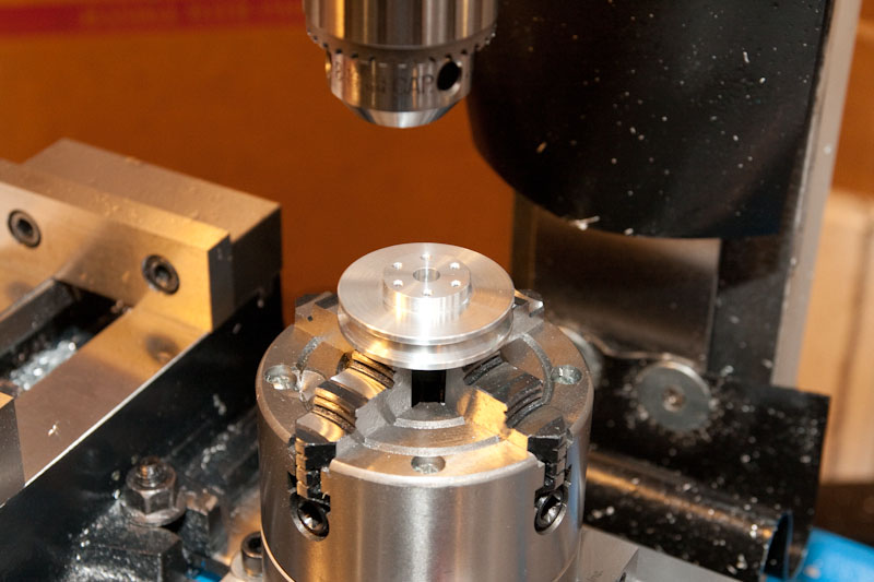
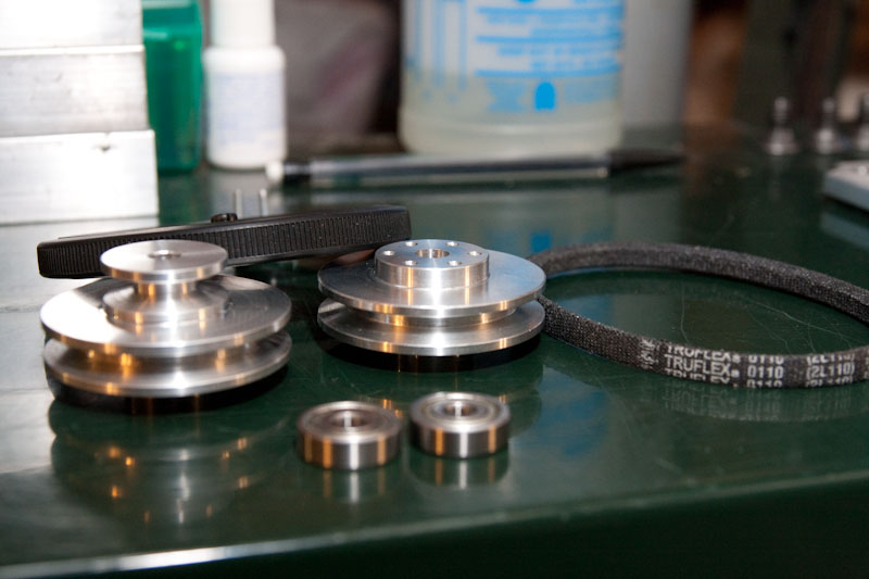
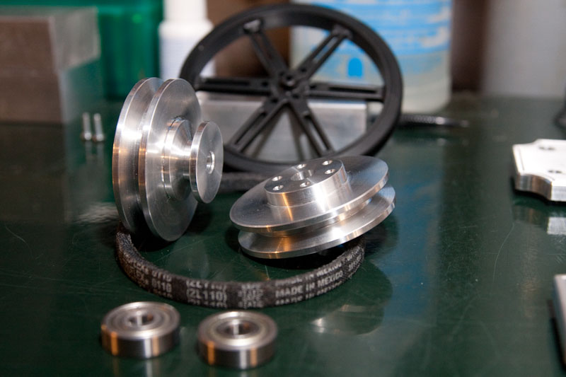
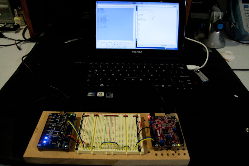


Comments
but they do have a shock absorbing quality that gears don't always offer,. for instance,
When slamming full speed into an opponents machine with your diamond blade running at full speed.
some gears might fail here, where as the well adjusted V-belt could survive the initial shock. then return to full speed.
Of course, chains and sprockets can take some shock, but still not as flexible as good old fashion rubber fan belts.
Gears have the least amount of "slop" and are necessary for any kind of repeatable accuracy, As they don't stretch..
Either way, if you are already spinning pulleys on your mill, then you might be interested in this web site.
-Tommy
can't get it on..... shave a bit more, can't get it on.... shave a bit more, still can't get it on... shave a bit more. Oops, slip fit, too much. Not a big deal though. Too much experimentation needed to make these press fits I need to be able to remove things. Some green LocTite should do the trick once I need them to stay put for a while.
Machined Parts: Shaft, Rear washer, Bearing Block, and Wheel Pulley
Bearings Assembled
The Complete Wheel Unit.
I'm interested in where you're going with the pulleys. It'll be a new experience for me so I'm all eyes on this one.
Ken Gracey
The machine is a converted PM-25MV mill, very similar to the Grizzly G0704. I spent about a year and a half converting it to CNC, starting by just adapting steppers to the ACME screws so I could make the parts needed to convert to ballscrews and design them the way I wanted. It's a decent machine for a guy at home. Holds about 0.003" of programmed dimensions as a pretty reliable number all over the table. Sticking to the center of travels and careful programming with light finish passes can get better results if I have to have that. It can take rather impressive cuts in AL and steel although steel still eats my lunch at times since little things you don't think of can bite you hard. I ruin tools much easier in steel. It's still a work in progress. Converting from gears to belts for the spindle drive and making a real enclosure for the electronics instead of the wooden jury-rigged box they live in right now. The controller is EMC2 which I think is really nice considering it's totally free. The final system will be running with EMC2 and a MESA FPGA card to off-load step/dir signals from the PC to the FPGA which will allow for higher rapids. Right now it's at 150 IPM and with the MESA cards I expect to be able to get 200 IPM plus for the X/Y axis.
I really think it was a great learning experience. A Tormach PCNC 770 would have been a faster way to get up and going making stuff with very similar work envelope but I have learned an immense amount in converting the machine that I would not have to draw on were I to just buy the turn-key machine but there are obvious drawbacks too. It's always going to be a conversion so every problem is mine to deal with and it will be a long road before I have the nice stuff like integral oiling, and flood coolant.... if ever. It's just mesmerizing though to watch this thing just hum along with a rooster-tail of metal flying out behind it going about making something I just drew up become a reality and to contemplate the fact that I live in a day where something like that is possible to have in a suburban basement.
Here's a few videos of the machine in action.
Long video showing the process of making a new bearing end-cap for the machine from start to finish:
http://www.youtube.com/watch?v=-jRUjQB1Ik0
Shorter video showing me making part of my Father-In-Law's Christmas present this year. New dresser handles that he can't break off!
http://www.youtube.com/watch?v=_w-QKo6ogbg
Good luck! Bob
Color me jealous! When I get around to turning my backyard shed into a shop, one of those just might find it's way sneaking in there.
It back in business and running at 5000RPM now vs my original 3000. Much improved and much quieter. I spent today working out the bugs in my CAM file and generating the GCode needed to finish out a bracket and test my strategy. Seems like it will all work out but my holding tabs on the final cutout operation were not big enough and the part dropped out in the roughing pass so it's going to be a tad oversized. At some point I will look for a way to correct that. For now it's workable.
The idea seems to have merrit and the little motor appears to have decent torque at moderate RPMs to where it feels roughly equal force is needed to stall the stepper at motor shaft as it is at the drive wheel. That was my goal. I think it will definately benefit from a timing pulley arrangement rather than V-Belts but as I said this was much easier to get up and going to test if the motor was ever going to have hope of moving any load. I think based on the feel of it, that it will be able to haul a few lbs around without too much issue.
Now that the bugs are worked out and tooling configured, I can probably turn out another bracket in an hour or two. The manual lathe work will take much longer.
Photos of the trial fitting:
The mill with newly fitted belt drive
Bob
However you would be amazed what you can do with a 10" drill press, a couple of mills, and one of these:
http://www.harborfreight.com/5-inch-drill-press-milling-vise-94276.html.
I am looking forward to seeing the finished project.
Bruce
http://www.harborfreight.com/12-lb-sledge-hammer-with-fiberglass-handle-94061.html
I concur, Dr. Bruce. Simplicity is key to success!
http://www.harborfreight.com/total-control-hacksaw-38075.html
I also concur with you Capt.Erco, but this is too extreme! Made an old man out of me
I'll leave milling on the drill press to those braver than I. My DP barely controls chatter in drilling, milling would be an unpleasant experience to be certain and the chuck would almost certainly drop from the JT arbor. I actually have a little X2 manual mill out in the garage that I have a little drill press table mounted up to. It serves quite well as a precise drill press as long as the holes are not much bigger than about 5/16" ad the work is not too tall. I despise milling on it though, the 0.0625"/turn hand-wheels are an abomination.
I am not a patient person. Without the CNC capability everything I did would be square or maybe angled.... setting up the rotary table and solving the work-holding puzzle on it was too much of a pain, avoided it wherever I could.
In fact, I should get a shiny new patent from the patent office today. YIPPEE
Anyhow, to get back on subject... I am very impressed with your metal work.
Bruce
I modified the wheel bearing block by not profiling the 'ears' like I did on the left side. I think the large disk being clamped to the bracket will be a better design. I'll have to make up another for the left side. After I get the shafts and pulleys finished for this side then it's not too far away from having something I can do my first testing against for weight capacity. Just a plywood board and a few screws would give me a basic start point while I begin to plan out the deck. I figure the deck will be 3/16" aluminum plate and can have a lot of cutouts to keep weight down but strength up.
Didn't know if there were any super compelling reasons to go with one over the others. I am looking at the castor design too. I have a tile floor with grout lines and I'm considering added some suspension action to the castor so it isn't banging into the grout line all the time. Then again, if the wheel or ball is wide enough it should act to smooth that out anyway. I know they aren't big bumps but repeated vibration is just asking to find something important and loosen it till it falls off.
I need to extend the wiring from the steppers to reach the top deck and get the castor attached with better than wood and double sticky tape and then I can start running it around to test out if it can handle another 3 to 4 lbs. I used fiber board just to get it mocked up but the way the drives are attached means the deck needs to provide ridgid support. Sheet or really thin plate just isn't going to cut it. Acetal is another posible but it's pricy stuff and I'm not sure if it saves a lot of weight over AL.
Sorry for the crappy cell picture but I had to take it and run to get to work this morning.
I am considering adding two rear omni wheels rather than a castor wheel, or making the castor with some type of spring suspension. The tile grout lines make for a rough ride for the little guy. I'll try to add some video this week.
There's the video. Can't see an option to embed. If you want to skip to the moving part just go to about the 6 minute mark. I'm sending this to non-robotics friends and family so I tried to explain it just a little in the beginning too.
Casters are just another harsh reality of robot economics... I hate casters too, but what can ya do?
The deck is going to be very sturdy with all that aluminium, looks like it's good for lots of payload pounds.
-Tommy
I did add code to allow for moving in inches instead of steps so it's possible now to tell it to move roughly so many inches and that is working well. That opens the door to being able to code the more advanced arc movements since telling each wheel to move so many inches should generate a particular arc segment. I'm then going to code some short-cuts for simple ones (90L, 90R, 180L, 180R).
Should start working on the deck this week or next. I now have the ability to powder coat at home so I can add a little color to it too.
Came up with a design for the rear wheels that I don't hate. Dont love it either but it's simple and re-uses parts from the belt system to mount the rear wheels on a bearing. Version 2 I want to put more asthetic work into but this should get me rolling. I need to finsh a few final details then load up the design into my CAM software and get going making the tool paths. One of my Wife's students is interested in the mechanical side so I have invited him over so he can do some work with me on the mill. Figure he'll get a kick out of watching it carve this stuff out.
Got a little further on the model tonight: