Prop1 Module Rev 1 - Pardon for another DIP-40 pins P8X32A ... (@ PropellerPowered)
 MacTuxLin
Posts: 821
Hello All,
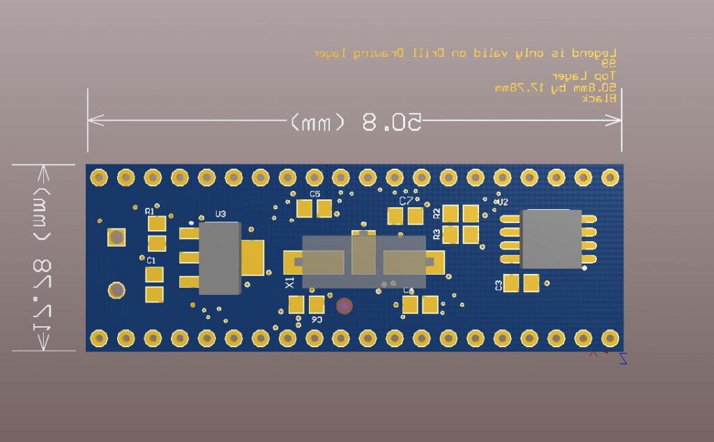
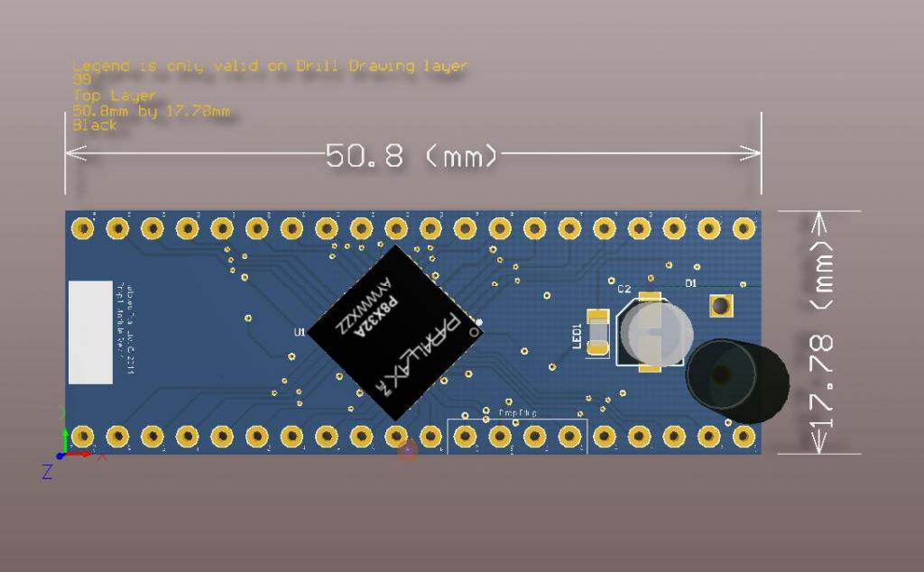
My initial plan for this design was for use within the company for programming, assembly, testing other boards but then I thought, why not sell this & earn a little cash for the company.
Main items on-board are:
- P8X32A-M44
- 5MHz crystal
- LD1117 (3v3)
- 24LC512 (64KB EEPROM)
So it's easy to place this onto a breadboard powered by a 9V battery. I have done some video tutorials which will be placed on the web-site to help new users play & learn Spin with this device.
I'm going to do another board revision before we sell but I was hoping the community could throw me some suggestion and/or enhancement needed to the new revision. Also, I'm thinking to send 1 or 2 units to prop veterans for reviews which I could place it on our company web-site when they go online in 2 or 3 week's time.
Thanks a lot.
~~~~~~~~~~~~~~~~[ BELOW ARE THE LATEST UPDATES ]~~~~~~~~~~~~~~~~
Prop 1 Module:
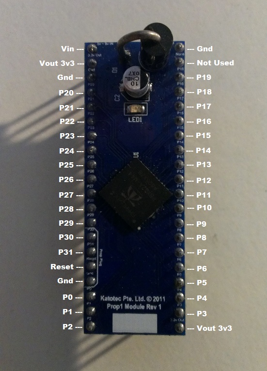
Schematics
Prop 1 Module Extended:
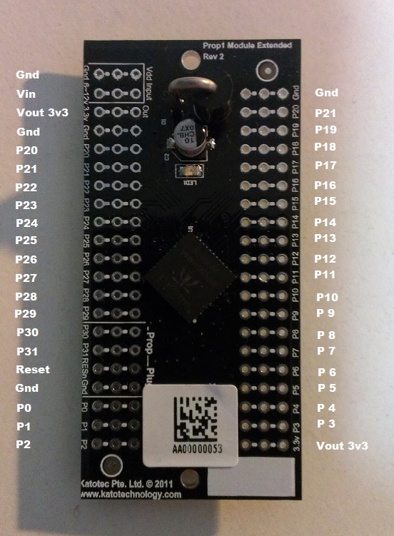
Schematics
Projects I did with these:
1. DS1307 Tester (Prop 1 Module)
2. Mini-Breadboard (still thinking...) (Prop 1 Module)
3. Retronitus with LM4990 (Audio Amp) (Prop 1 Module Extended)
4. Portable Mic Recorder (Prop 1 Module Extended)
It was just for fun to play with sigma-delta (mounting the SMD resistors & caps on-board) & saving the sounds to MicroSD card.
My initial plan for this design was for use within the company for programming, assembly, testing other boards but then I thought, why not sell this & earn a little cash for the company.
Main items on-board are:
- P8X32A-M44
- 5MHz crystal
- LD1117 (3v3)
- 24LC512 (64KB EEPROM)
So it's easy to place this onto a breadboard powered by a 9V battery. I have done some video tutorials which will be placed on the web-site to help new users play & learn Spin with this device.
I'm going to do another board revision before we sell but I was hoping the community could throw me some suggestion and/or enhancement needed to the new revision. Also, I'm thinking to send 1 or 2 units to prop veterans for reviews which I could place it on our company web-site when they go online in 2 or 3 week's time.
Thanks a lot.
~~~~~~~~~~~~~~~~[ BELOW ARE THE LATEST UPDATES ]~~~~~~~~~~~~~~~~
Prop 1 Module:

Schematics
Prop 1 Module Extended:

Schematics
Projects I did with these:
1. DS1307 Tester (Prop 1 Module)
2. Mini-Breadboard (still thinking...) (Prop 1 Module)
3. Retronitus with LM4990 (Audio Amp) (Prop 1 Module Extended)
4. Portable Mic Recorder (Prop 1 Module Extended)
It was just for fun to play with sigma-delta (mounting the SMD resistors & caps on-board) & saving the sounds to MicroSD card.


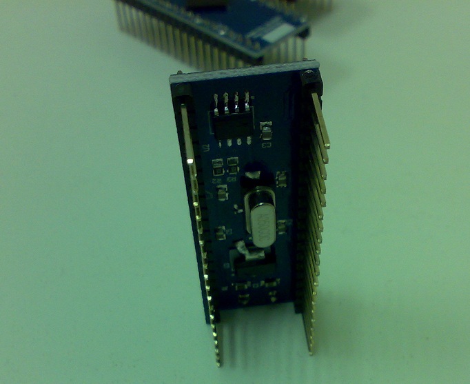
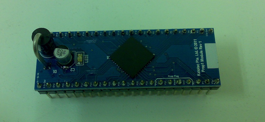
Comments
I think it's a good idea. Put a few up for sale and see how it goes.
Header optional would be a big + (that way I wouldn't have to remove those pins.)
Given that, I'd yank the LD.... on my own and run it from a 7803SR (ext.) - from a 9V battery, for a long time.
One thing that I always wonder: The 40 pin DIP modules always seem too wide for a bead board. There's always three rows of holes covered.
Couldn't a multilayer board be made such that the headers allowed both rows of pins on the opposite sides of the same edge? That way, the module could plug edge-wise into the bread board, and leave all the remaining holes open. Also, if the same pad pattern were duplicated on the opposite side of the board, we'd have the pins on one side and available connections of the other.
@Allen. Thanks. That's a great help! I'll add that to the new revision.
@Prof_braino. Thanks. From the cost perspective, anything more than 2-layer is expensive to fabricate, though but good thought.
Have you given any thought to using a DIP40 pinout instead of a custom pinout? You could still have a prop plug connection by utilizing a header at one end. I have received numerous positive comments on my M44D40+ module because I went that route. Also, in regards to the added rows for additional circuitry, you can make 3x20 proto strips and have those as options for your module. This allows you to keep the minimal size footprint for the standard version. This picture shows my module with a 3x20 header added to one side to add functionality.
As for the holes being tied together on the wider module, I would tie the first two together (the inner and middle rows) but leave the outer row unconnected. This allows for the best verstility.
As I saw it, the whole pad (of 3 places) should be dedicated to the associated pin.
It's a Propeller-to-go; the crystal, caps, and everything else taken care of, and one can route wires out to whatever, wherever.
Otherwise it turns into an experimenter board without enough holes, versatility that isn't.
@Allen, thank you. I like the name "Propeller-to-go"
National has a complete line of lowdrop low quiescent current.. here...
Yes Linear's parts are rather expensive
Thanks.
Those are going to be great!
Jeff
You need to check your board dimensions on your product pages.....unless they ARE REALLY BIG PC boards!
The only part of the description I copy/pasted from @MacTuxLin without looking carefully at it.
Fixed! Thanks - No blame to @MacTuxLin, our system of measurement is really stupid here.
Jeff
Is there a schematic for this module....can't find it on the propeller powered.com website
Sorry, should have posted the schematics much earlier. Here they are:
Prop1 Module
Prop1 Module Extended
Congratulations on getting these built and in stock with Jeff! They look like great prototyping tools and something that will go on my growing list of "things to buy from Jeff"!
Looks like Prop pin P1 of Connector 1 in both schematics should be labeled P2 instead of P20 (otherwise, there's no P2).
Also, for the extended board/schematic, is Prop pin P20 (not P2) going to both connectors (CN1-17 & CN2-20) by design?
Maybe you can add links for these schematics to Propellerpowered when finailized (if you haven't already).
Thanks for designing these boards and making them available. --Jim
Thank you mindrobots.
I'll be posting some projects I did with these boards.