

Reverse Polarity Protection Using a Smart Low-Side Switch ( IPS2041)
 DavidM
Posts: 640
DavidM
Posts: 640
HI,
I had this idea today, would the following work as a..
1) Reverse polarity Protection Circuit ( From battery leads connected in reverse) ?
2) Short Circuit Protection
3) Current Overload
I have chosen the IPS2041 Device ( From International Rectifier) as I am using this part elsewhere in another design. This Smart,Low-Side Switch has logic level input as the "GATE", requiring at least 4V+ to turn on the mosfet.
This device also has a built in Current/Thermal shutdown set at 5Amps, So If I had a short circuit , Or a current Overload situation, The device will turn "OFF"
My Theory of Operation ( Me thinks?)
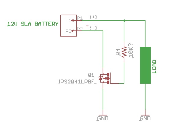
1) When the battery leads are accidentally connected in reverse , there is no "gate" drive so NOTHING Happens ( I hope ), If the polarity of the leads is connected CORRECTLY, The gate is pulled "HIGH", ( I not sure if just a 10K resistor would work) and current is allowed to flow through the MOSFET.
2) If there is a short circuit anywhere on the load ( Which is a circuit, rather than a single load device) then the Built in Overload in the MOSFET will activate and turn itself off. The same goes for Over current ( in this case the device is set to 5Amps)
What Do You think?
( I have attached my example Schematic, And the Data-sheet for the mosfet)
thanks
Dave M
I had this idea today, would the following work as a..
1) Reverse polarity Protection Circuit ( From battery leads connected in reverse) ?
2) Short Circuit Protection
3) Current Overload
I have chosen the IPS2041 Device ( From International Rectifier) as I am using this part elsewhere in another design. This Smart,Low-Side Switch has logic level input as the "GATE", requiring at least 4V+ to turn on the mosfet.
This device also has a built in Current/Thermal shutdown set at 5Amps, So If I had a short circuit , Or a current Overload situation, The device will turn "OFF"
My Theory of Operation ( Me thinks?)
1) When the battery leads are accidentally connected in reverse , there is no "gate" drive so NOTHING Happens ( I hope ), If the polarity of the leads is connected CORRECTLY, The gate is pulled "HIGH", ( I not sure if just a 10K resistor would work) and current is allowed to flow through the MOSFET.
2) If there is a short circuit anywhere on the load ( Which is a circuit, rather than a single load device) then the Built in Overload in the MOSFET will activate and turn itself off. The same goes for Over current ( in this case the device is set to 5Amps)
What Do You think?
( I have attached my example Schematic, And the Data-sheet for the mosfet)
thanks
Dave M
555 x 430 - 24K

Comments
But comeing from a DC perspective . I have a tendincy to use a case as a 12GND along with a GND buss or rail so if the user decided to use the Case not the marked ( -) input they would bypass the entire circuit .
I use a BIG diode and a fuse . Or just a Shocky diode . or a relay
One is a crowbar approch . has 0 loss but needs a fuse after a RP event . the other is more lossy but needs no reset .
A ) RP dioded is accross the input so that if a RP is placed Its shunted . Now Mr Diode can not take a 100 amp surge for long so I have a fuse rated at 2X running current .
most SLA batts will do enough amps to pop that fuse in a Micro second .
C) Relay and a diode . If the Polatrye is wrong it pops a relay and a LED comes on to warn .
relay is NC for non RP .
In your schematic the Bulk diode is drawn incorrectly. (<-- Looks like you used a P-mos rather than an N-mos) In order for this configuration to work, you would need two transistors (Both N-mos or both P-mos) that are connected back to back. Otherwise, the Bulk diode will conduct when the battery polarity is reversed. i.e. for two N-mos, one Source going to the negative supply, and the other Source going to the load. Both Drains and Both Gates would be tied together. The Gates would connect to the positive supply through a 1k or so resistor (a 10k is probably ok though)
I was originally planning to use a Diode/PolySwitch in series combo, But I read somewhere that the forward voltage of the diode can reduce the life of a battery, I need this circuit to MAINLY Protect against Current Overload, ( As well as Internal Short Circuit) . When I look at the specs for polyswitch's they all seem to have a LONG TRIP Time (in seconds), So I am not sure which polyswitch to use. One I have used before is a MINISMDC110F/24
Hi Beau,
Yes, The symbol for the mosfet is wrong in the schematic, I just grabbed any mosfet ( a p-channel ) from the eagle library , Have a Look at the diagram ( page 1) in the IPS2041 datasheet, its actually a low side mosfet, with additional control circuity built in to control it. While this device behaves like a P-Channel Mosfet, Its gate is really a LOGIC LEVEL Input (I.e A HIGH turns on the Mosfet) , me thinks? The reason I want to use this is ( a) I am using this device elsewhere, (b) I want to take advantage of its built in current limit features.
Dave M
"Have a Look at the diagram ( page 1) in the IPS2041 datasheet, its actually a low side mosfet...While this device behaves like a P-Channel Mosfet, Its gate is really a LOGIC LEVEL Input" ... Yes, I have looked at the datasheet, and even though the device behaves like a P-Channel Mosfet you still have the Bulk diode to deal with, which is why you need at minimum two mosfet transistors to provide a complete disconnect when/if the power is applied in reverse. If only one transistor is used it will turn ON like it is supposed to when power is applied correctly, however the Bulk diode will conduct when the power is reversed.
Thanks for replying,
OK Forget this idea ( for now)
I remember a post here some time ago about the double mosfet idea, but I cannot find the post, there was a diagram attached to it as well.
I am now thinking it might be easier to just use a SERIES DIODE. ( and maybe a polyswitch for over current )
I am already about to use a V10P10 Barrier Schottky diode ( For my Boost regulator circuit ) , So to keep the BOM simpler, I could use this Diode for the task. It has a voltage drop of about 0.5V.
Do you have a diagram of the Double mosfet Circuit?
Thanks
Dave M
However, I think the goal here is to avoid the diode drop(s) and still provide reverse polarity protection.
Choosing a mosfet with a low RdsON will provide the best results, but here are a few schematics using both back-to-back NMOS transistors as well as back-to-back PMOS transistors.
That the one!, And yes, A Single Diode is the simplest, but to get the low voltage drop, or no voltage drop we need to use the mosfets as you have shown in your diagram.
I have a bunch of FQP8P10 - TO-220 Mosfets, These have the following specs
-8.0A, -100V, RDS(on) = 0.53Ω @VGS = -10 V
So using a 12v battery should be fine for switching on the mosfet fully?
I will make a test circuit ( Protection before the load -pMOS) and get back to you.
QUESTION - In what situation would you have the Protection circuit Before ( pMOS) or After (nMOS) the LOAD, And does it matter?
Thanks
Dave M
I made up a breadboard using the MOSFET I mentioned.
The schematic WORKS!
I tested both Correct Polarity and Incorrect Polarity, both work
I tested the voltage drop and there appears to be none! ( As opposed to the DIODE ONLY Method)
Now, I have found several SO-8 Package DUAL P-Channel Mosfets ( Digikey ) eg STS4DPF30L
I am drawing a schematic and PCB Layout to show how this can be implemented.
Q1) I would still need a SHORT CIRCUIT / OVERCURRENT Protection, ( I think I can do this elsewhere in the circuit)
Q2) The drain pins ( 5 to 8 ) On a SO-8 Package are all joined together, So Does this need PCB Heatsink/Pad area?
Thanks
Dave M