

Graphcs Slave Propeller Platform Module
 Microcontrolled
Posts: 2,461
Microcontrolled
Posts: 2,461
I am about to get this PCB made by BatchPCB for a test run... thought it might be of interest. As assumed by the title, this board is to support my Graphics Slave program I made about a year ago, when I released only binaries. Now, however, I have decided to release the full source code.
Download it here: http://microcontrolled.com/GraphicsSlaveV.1.3.zip
On a mobile or don't want to download? View it here: http://microcontrolled.com/GraphicsSlaveMobileView.php
Looking back, I realize how sloppy my code was. :-)
If you don't know exactly what the Graphics Slave is, it is a module that separates the job of high-end graphics functions into 2 Propellers to save RAM. The Propellers talk via serial communication. It has an easy to understand command set and does things like draw lines, dots, text, and more. Simple animations on it are fluid at 115200 baud. If you add lots of items on the screen, however, the animation gets choppy.
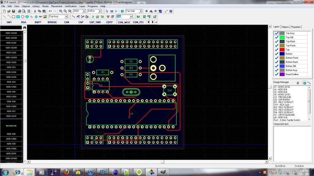
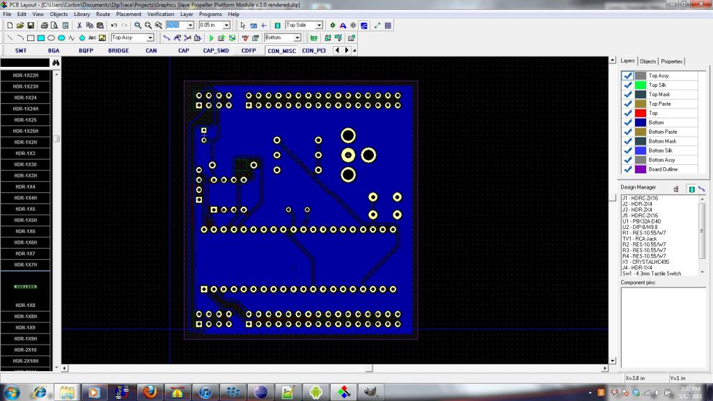
I am working on a new version (1.4) with mouse and cursor support, so if that works I'll have to modify the PCB accordingly. Here are some screen shots of the board I've designed:


If there is enough demand, I'll get a run of these made, but due to the high cost of PCB runs (cheapest $110), there will have to be a good bit of demand. OBC said in another thread that he had been working on the same type of thing, so he is welcome to pitch in and collaborate with me on this. :-)
Thanks,
Microcontrolled
Download it here: http://microcontrolled.com/GraphicsSlaveV.1.3.zip
On a mobile or don't want to download? View it here: http://microcontrolled.com/GraphicsSlaveMobileView.php
Looking back, I realize how sloppy my code was. :-)
If you don't know exactly what the Graphics Slave is, it is a module that separates the job of high-end graphics functions into 2 Propellers to save RAM. The Propellers talk via serial communication. It has an easy to understand command set and does things like draw lines, dots, text, and more. Simple animations on it are fluid at 115200 baud. If you add lots of items on the screen, however, the animation gets choppy.
I am working on a new version (1.4) with mouse and cursor support, so if that works I'll have to modify the PCB accordingly. Here are some screen shots of the board I've designed:
If there is enough demand, I'll get a run of these made, but due to the high cost of PCB runs (cheapest $110), there will have to be a good bit of demand. OBC said in another thread that he had been working on the same type of thing, so he is welcome to pitch in and collaborate with me on this. :-)
Thanks,
Microcontrolled
1024 x 576 - 110K
1024 x 576 - 103K
Comments
Anyway.. How about expanding this to include stereo audio output? Room?
Also, I'd like to see an 8 I/O connections between the first and second propeller with trace lines which can be cut, with the ability to add resistors to pull the pins low to keep them from floating. I'll try to dig up some examples of what I have in mind later.
Here's a link to the thread for the one I'm working on..
http://www.savagecircuits.com/forums/showthread.php?505-160x192-High-Color-1-byte-Pixel-sound-interesting
OBC
OBC
I've managed to cram in PS/2, and audio with external speaker transistor amplifiers and a selection brick! I also added a Parallel interface with 8 pullup/pulldown resistors, selectable through another brick (I don't know what they are called, terminal maybe?). All without changing the board size! I've been working on the drivers too but I'll post about that when I have something solid working.
Thanks,
Microcontrolled
P.S. If you know a cheaper PCB fab please post!
I downloaded the zip file but didn't find the video driver in it.
I have a request, though. It looks like the board is wider than the standard GG Propeller Platform board. It will stick out on either side. Also, I expect it will not be able to be used with the enclosure sold by Parallax.
Can you get the outside traces inside the headers? If not, it may be ok to reduce the headers to a single row. If people start using stacking headers between the boards (I almost always do), the extra rows may be redundant. They are useful on a protoboard, but not on one where all the functionality is already wired.
You have a lot of resistors and the crystal under the Prop. Do you intend for them to be on the same side as the Prop or on the opposite side? Do you have a socket in mind that you know will handle these components? It might be a bit tight.
Also, it's hard to tell, but you have a lot of long traces I'd probably try to reroute. I can't really see what's going on on the other side of the board that clearly so I can't tell for sure.
Also, if you intend the board to be stackable (sit between the Propeller Platform and another board on top), you could extend the board lengthwise a little and put the connectors off to one side. This would make the board not fit in a GG case, but might give you some extra room as well as allowing it to be the meat in the sandwich without the upper board hitting the connectors.
Just food for thought..
OBC
I have again revised the board. Diptrace doesn't like the traces being this close and gives me warnings, but it was the only way I could get the board small enough to fit inside the ever-important enclosure. I've re-positioned the Propeller Chip and have switched to single row headers. Now all the peripherals are on one side, which is more practical for an enclosure.
OBC
I'm having some trouble following the bottom layer of the board - the dark blue traces in the jpg are tough to see on my monitor (by the way, if possible png or some other lossless format would be better than jpg for something like this). But it looks like you have a lot of really long traces traveling around the outside of the board. I expect that you can keep rearranging things to remove a number of these.
@schill: I'll upload in a lossless format next time.
Looks like a good design!
One thing you could do if board real-estate is tight is use a stereo audio jack (something like this) instead of the current RCA jack and then put out mono sound and video (using an iPod cable, or something like this) for a connection. Granted, you said RAM is tight, and any extra capacitors/resistors on the board may not work. Just thought I would at least mention it.
The inside layer? If I understand correctly this would mean that it can't plug into the propeller platform board which uses the outer rows of pins. I must be misunderstanding.
Also, I don't see any decoupling capacitors on the prop's power pins.
If you have room for an audio connector on the board but no room for the driver, you can still put the connector there. Just feed it from the Prop on the propeller platform board instead of the graphics slave board.
@Schill: This is what I mean by inside pins:
I like the idea of having audio controlled by the main Propeller, as it has access to the SD card anyway.
I'll add decoupling caps on the prop pins.
Doesn't that mean you won't be able to plug it into the board in your picture?
That board, in turn, could have female headers on the outside so that another board could stack on it. You can keep alternating ad infinitum if you want.
But, if you use stacking headers (female headers with long pins) you only need one row and you gain the extra board space.
Micro,
From your cost quote, I am guessing that you are looking at Gold Phoenix - they are pretty good, very low cost and fairly quick, and I like the job they did for me... But - the $110 price is for 155 square inches; one square meter is about 1550 square inches, or the Gold Phoenix deal is for about 1/10th of a square meter. If I have it wrong, please let us know; I would definitely want to look into your source.
BTW: this looks like a great project! I need something like this for a couple of projects I have on the back burners.
@Schill: I get it, thanks for the help.
Bummer! I thought that you had given me a triple Jackpot! Oh well, I guess that I already had the best price around.