

Modified Panels for Parallax Propeller C3 Enclosures
 schill
Posts: 741
schill
Posts: 741
I've designed a set of modified panels for the C3 enclosure that Parallax sells. These panels have large generic openings that can be used to access the C3 while it's in the enclosure or to run wires in and out.
Propeller C3:
http://www.parallax.com/StoreSearchResults/tabid/768/txtSearch/c3/List/0/SortField/4/ProductID/721/Default.aspx
http://www.parallax.com/StoreSearchResults/tabid/768/txtSearch/c3/List/0/SortField/4/ProductID/724/Default.aspx
Propeller C3 Transparent Enclosure:
http://www.parallax.com/StoreSearchResults/tabid/768/txtSearch/c3/List/0/SortField/4/ProductID/725/Default.aspx
Parallax provides a DXF file for the panels in their enclosure so it was very easy to modify this file to create new panels that otherwise closely match the Parallax panels. It is available from the page linked above.
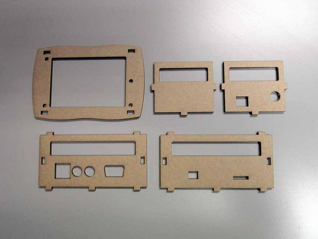
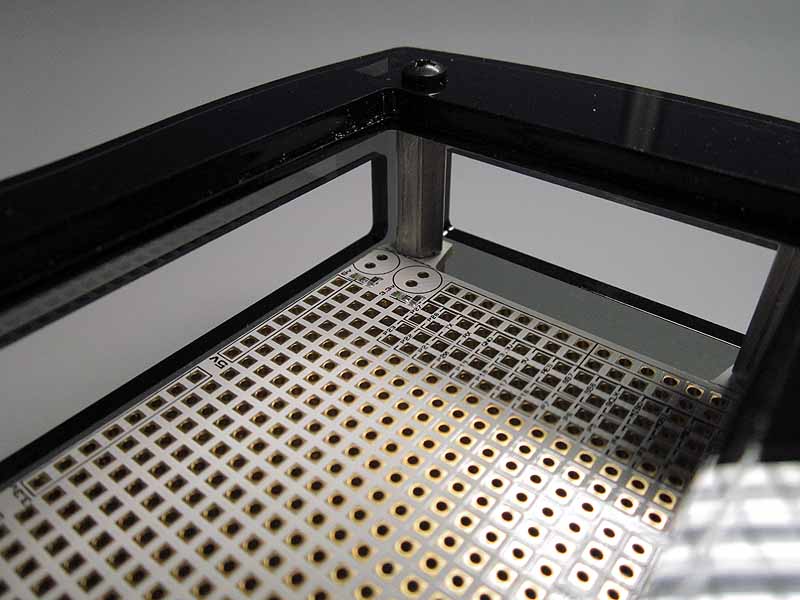
The modified top panel has a large opening in the middle to access the interior. I put a 1/8" hole (roughly #4 screw size) in the middle of the opening so that a cover or access panel can be made using the cutout. Additional support is required to prevent the cover from falling through the hole. More about that later.
The top panel can be used with either the full or half height walls from Parallax.

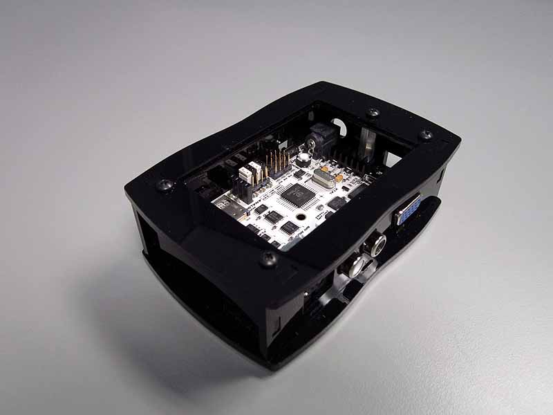
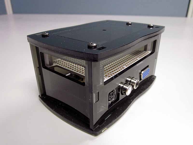

The side panels are based on the full height walls from Parallax and all have most of the upper half of the panel wide open. I slightly enlarged the size of the hole for the PS/2 jack because it seemed to be a little tight for one of my C3s. The new hole is a few hundredths of an inch larger than the original hole in the Parallax drawing.
These panels are shown in the file "C3 with openings no labels v2.pdf".
I don't imagine that most applications will require more than one or two sides with openings. These panels can be mixed with the original panels from Parallax without any problems.
I have had these panels cut from 1/8" (3mm) acrylic and they are compatible with the Parallax panels.
I have made an additional type of top panel and the two parts of these are shown in the second drawing (C3 dual top.pdf). One of these is identical to the previous top panel. The other has the cutout reduced by 0.05" on each side (0.10" total in each dimension). These are intended to be cut out of material thinner than the 1/8" used for the standard panels (I used 1/16" acrylic). The panel with the smaller cutout can be placed underneath the one with the standard cutout to create a lip that supports one of the larger cutouts so that it functions as a cover.
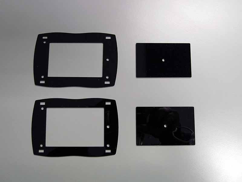
The two 1/16" panels can be stacked together to provide a 1/8" thick cover or the 1/16" panel with the smaller cutout can be placed underneath the standard 1/8" thick plate. When used with the 1/8" plate, this means that the tabs from the side walls are recessed 1/16" below the top of the enclosure but this doesn't look too bad.
The cover itself can be one of the 1/8" or 1/16" cutouts - matching the upper layer on the top panel to create a "smooth" top. The two 1/16" cutouts can also be stacked and held together with a single bolt and nut through the center hole to create a removable cover with a lip that complements the lip in the top panel. The nut and bolt provide a convenient knob for removing the cover (in the pictures below I used a bolt and threaded standoff). Of course only the top cutout is really required for the cover. The bolt and nut can also be used (obviously) to provide a knob in either case.
Clear "Scotch" tape makes a good hinge for the cover panels if desired and doesn't look too bad if you keep dust out from underneath it. The shiny stuff looks better than the "invisible" kind. It's also easy to remove if you no longer want the hinge.
I've attached DXF and PDF files for my modified panels. The PDF files are not to scale - they will not be the correct size when printed. Both file types have a reference 1x1 inch square for purposes of determining scale. The DXF files should be enough to enable anyone with access to a laser cutter to make them. Of course, they could also be used for any other fabrication method - manual or automated.
The files are freely available for anyone to do whatever they want with them. The only restriction I place on them is that they not be used in any way that conflicts with any restrictions Parallax may place on the original files.
Edit: I have designed another version of the top panel. It is posted below.
Propeller C3:
http://www.parallax.com/StoreSearchResults/tabid/768/txtSearch/c3/List/0/SortField/4/ProductID/721/Default.aspx
http://www.parallax.com/StoreSearchResults/tabid/768/txtSearch/c3/List/0/SortField/4/ProductID/724/Default.aspx
Propeller C3 Transparent Enclosure:
http://www.parallax.com/StoreSearchResults/tabid/768/txtSearch/c3/List/0/SortField/4/ProductID/725/Default.aspx
Parallax provides a DXF file for the panels in their enclosure so it was very easy to modify this file to create new panels that otherwise closely match the Parallax panels. It is available from the page linked above.
The modified top panel has a large opening in the middle to access the interior. I put a 1/8" hole (roughly #4 screw size) in the middle of the opening so that a cover or access panel can be made using the cutout. Additional support is required to prevent the cover from falling through the hole. More about that later.
The top panel can be used with either the full or half height walls from Parallax.
The side panels are based on the full height walls from Parallax and all have most of the upper half of the panel wide open. I slightly enlarged the size of the hole for the PS/2 jack because it seemed to be a little tight for one of my C3s. The new hole is a few hundredths of an inch larger than the original hole in the Parallax drawing.
These panels are shown in the file "C3 with openings no labels v2.pdf".
I don't imagine that most applications will require more than one or two sides with openings. These panels can be mixed with the original panels from Parallax without any problems.
I have had these panels cut from 1/8" (3mm) acrylic and they are compatible with the Parallax panels.
I have made an additional type of top panel and the two parts of these are shown in the second drawing (C3 dual top.pdf). One of these is identical to the previous top panel. The other has the cutout reduced by 0.05" on each side (0.10" total in each dimension). These are intended to be cut out of material thinner than the 1/8" used for the standard panels (I used 1/16" acrylic). The panel with the smaller cutout can be placed underneath the one with the standard cutout to create a lip that supports one of the larger cutouts so that it functions as a cover.
The two 1/16" panels can be stacked together to provide a 1/8" thick cover or the 1/16" panel with the smaller cutout can be placed underneath the standard 1/8" thick plate. When used with the 1/8" plate, this means that the tabs from the side walls are recessed 1/16" below the top of the enclosure but this doesn't look too bad.
The cover itself can be one of the 1/8" or 1/16" cutouts - matching the upper layer on the top panel to create a "smooth" top. The two 1/16" cutouts can also be stacked and held together with a single bolt and nut through the center hole to create a removable cover with a lip that complements the lip in the top panel. The nut and bolt provide a convenient knob for removing the cover (in the pictures below I used a bolt and threaded standoff). Of course only the top cutout is really required for the cover. The bolt and nut can also be used (obviously) to provide a knob in either case.
Clear "Scotch" tape makes a good hinge for the cover panels if desired and doesn't look too bad if you keep dust out from underneath it. The shiny stuff looks better than the "invisible" kind. It's also easy to remove if you no longer want the hinge.
I've attached DXF and PDF files for my modified panels. The PDF files are not to scale - they will not be the correct size when printed. Both file types have a reference 1x1 inch square for purposes of determining scale. The DXF files should be enough to enable anyone with access to a laser cutter to make them. Of course, they could also be used for any other fabrication method - manual or automated.
The files are freely available for anyone to do whatever they want with them. The only restriction I place on them is that they not be used in any way that conflicts with any restrictions Parallax may place on the original files.
Edit: I have designed another version of the top panel. It is posted below.


Comments
I like your mods.
Paul
The hole in this panel extends to halfway between the inner and outer faces of the walls on two sides. This gives you access edge-to-edge across the short width of the board. In addition, because the hole overlaps the top of the walls, the walls will support the access panel.
Because I've minimized the support area for this panel, in order to get a larger hole, it is easier to drop the panel into the enclosure. But since this will probably be used primarily during development I think this is an ok tradeoff. And the tape hinge described in the previous post does a good job of keeping it from falling in.
I've attached dxf and pdf files for the new top panel. The dxf should be sufficient to have the panel laser cut. I've also attached a number of pictures.