

New Power Solution for the Stingray and more...
 Matt Gilliland
Posts: 1,406
Matt Gilliland
Posts: 1,406
Hi Everybody -
This is coming soon... It's an integrated self-contained Li-Ion Battery Power Supply and Charging System.
This is the Prototype...
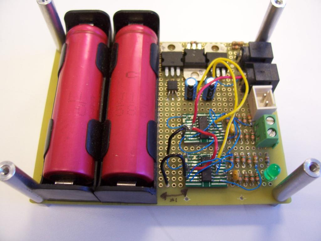
The 3" x 4" PCB contains two Li-Ion Cells and independent charging systems for each.
Basically, circuit operation is as follows:
When a wall-wart is plugged into one of the barrel jacks, each cell is electrically isolated from each other, and each charging circuit independently (and properly) charges each cell. There are two LED's showing charging status for each cell (fault, over/under temp, charging, and fully charged).
When the wall-wart is removed from the circuit, the cells are automatically "switched" into a series solution, delivering about 8vdc @ (in the case of these cells) 2.4 Amp hours.
Originally this circuit was designed as an upgrade for the Stingray battery pack with a slightly different form factor. However, by putting it on a 3x4 PCB it becomes *stackable* with many of our standard boards (like the BOE, Prop Proto Board, etc.).
And it works nicely as a Stingray solution as well. The power jack is easily accessible from the rear opening of the Stingray - plug in a wall wart and you're done - no battery removal/replacement required.
The theory being that now you could have an integrated solution (power and charger) on a single PCB - no more need to remove batteries and place them in a separate charger (or worse, throw them alkalines away).
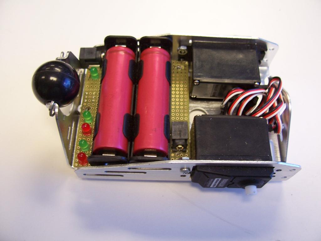
And now for something really cool...The same circuit in the belly of a BOEBOT. No more "AA" alkalines, no more removing rechargables to put into a separate charger.
This pic is a non-functioning Form Factor test board...
More to come...
This is coming soon... It's an integrated self-contained Li-Ion Battery Power Supply and Charging System.
This is the Prototype...
The 3" x 4" PCB contains two Li-Ion Cells and independent charging systems for each.
Basically, circuit operation is as follows:
When a wall-wart is plugged into one of the barrel jacks, each cell is electrically isolated from each other, and each charging circuit independently (and properly) charges each cell. There are two LED's showing charging status for each cell (fault, over/under temp, charging, and fully charged).
When the wall-wart is removed from the circuit, the cells are automatically "switched" into a series solution, delivering about 8vdc @ (in the case of these cells) 2.4 Amp hours.
Originally this circuit was designed as an upgrade for the Stingray battery pack with a slightly different form factor. However, by putting it on a 3x4 PCB it becomes *stackable* with many of our standard boards (like the BOE, Prop Proto Board, etc.).
And it works nicely as a Stingray solution as well. The power jack is easily accessible from the rear opening of the Stingray - plug in a wall wart and you're done - no battery removal/replacement required.
The theory being that now you could have an integrated solution (power and charger) on a single PCB - no more need to remove batteries and place them in a separate charger (or worse, throw them alkalines away).
And now for something really cool...The same circuit in the belly of a BOEBOT. No more "AA" alkalines, no more removing rechargables to put into a separate charger.
This pic is a non-functioning Form Factor test board...
More to come...

1024 x 768 - 78K

1024 x 768 - 64K
Comments
Also, what kind of current can you pull from those small cells? Will it be enough to run the motors at full power with load?
John Abshier
When a wall-wart is plugged into one of the barrel jacks, each cell is electrically isolated from each other, and each charging circuit independently (and properly) charges each cell. There are two LED's showing charging status for each cell (fault, over/under temp, charging, and fully charged).
Please explain this in more detail on how this is done Thanks
Yes, you can run the motors at the slightly higher voltage. The 7.2v is a nominal rating for the motors, they can handle a little more will no ill effects.
As far as run-time, we've only been able to do a couple of tests thus far, but the early indicators suggest that we should see a longer run-time with the Lithium pack, vs Alkaline "disposables" - maybe around 15%+ or so?. We have no data on how they would stack up against NiMH rechargeables - any of you run NiMH in the Stingray?
The cells are the standard "18650" form factor which is found in most laptops. They're not all that small (as may be indicated by the pic) - they are rated at 3.7 volts, 2.2 amps.
Interesting note: The 18650 cell (that we're using in this product) is the building block of the Tesla Roadster Electric Car. Only difference is that our "system" has two cells, and the Roadster has a "brick" of 6,831 individual 18650 cells. Yes, you read that right.
We also kind of took a cue from Tesla that it's way more convenient to have the charger always with the cells - no cell removal (for charging) is necessary. That way, as long as there's an outlet you can re-fuel your car, er...BoeBot / Stingray.
That being said, yes you can remove the cells and replace them with new ones when these wear out. Cell ratings on the one's that may come with the Board indicate that they should retain 90% of their charge capacity after 400 cycles, and their life is rated at >500 cycles (although we haven't tested this yet).
-Matt
Each individual cell has internal protections built-in for both over-voltage and over-discharging (below 2.5v).
Although you can charge Li-Ions "in series" - best practice for charging Li-Ions seems to be when each cell is isolated and individually monitored by a separate charging circuit. Therefore, the cells (which are normally connected in series for 8v) are electrically disconnected from each other, and the output power jack is "dead".
However, that's not the end of the story. The molex connector may be old news...
Suffice it to say (for now), that yes John, you can have the "application" be powered or not powered depending on how you use the "jack system" :-)
The charger looks great. Nice job on that. The BoeBot/Stingray crossover is a brilliant idea. I'll buy one!
If you are looking for another project, how about a "Propeller Cookbook". I loved those books (remember we met at UPEW?). They got me hooked on Stamps. You could show all of us Propeller newbies how to get the Stingray level translator to work, wire up sensors at 3.3V, drive MOSFET's at 3.3 V, and so on.
Sorry if this belongs in a new thread. I couldn't resist.
Rich H
Sorry that wasn't clear-er. The power output is not switched on/off via the jacks. There's a small network of transistors that do that in a solid state manner. Also, by breaking the electrical connection between the two cells (that are in series with each other when delivering power), each cell is individually monitored for voltage, current, and temperature. The charging circuit shuts down on either cell when a out-of-normal condition occurs.
Although the Li-Ions can be charged while delivering current to an extra "load", the optimum way to charge them is when they (the cells) are the only thing connected to the charging system. No need to worry about the charging of two cells in series being "out of balance".
@ Rich - No compatibility with A123's. We're using mature Li-Ion cells that are produced by the billions each year. My laptop is running on them now - in my lap...your's probably is too:-)
-Matt
Thank You for your reply Now I understand how you are doing this
Is there an UpDate to when this Item will be for sale I could use few of them very badly
Nice power supply. Now drop the gear ratio in thse Stingray gearmotors!
I'm told by manufacturing that it should be in stock in about two weeks. (they're really busy, and that's the soonest they can get it into the pipeline).
The documentation is done, and I'm pretty sure that all the components are in stock, so it's just a matter of getting a "build-slot" in our p-n-p machinery haven.
The board will be separate from the cells (so you can use any "18650" cell you wish - either from us or anyone else). We will be carrying only one type for now: The Tenergy 3.7 volt, 2600mAh PCB protected version. We highly recommend not using the unprotected versions for a couple of reasons:
First, protected cells will self-disconnect when their voltage drops below 2.5 volts. This prevents the cells from wearing out prematurely (this protection results in far greater number of charge/dis-charge cycles). In the case of the Boe-bot version (which is not quite ready for production yet), the number of cycles can go well beyond 500 cycles, perhaps closer to 1000 (although there's no way I've had time to verify these numbers. At two cycles per day (charge-time + discharge-time), we wouldn't have any real-world data till sometime next year.)
However, for power capabilities/longevity as it stands now, the Boe-bot version (similar circuit, but different form factor) has a projected run distance of over 4 miles for the little guy.
And second, although there's an on board 2 amp fuse, the protected cells also come with an internal fuse (usually set at 3 amps). It's just another safeguard against shorting the terminals, and not allowing the cells to generate too much internal heat.
I'll let you know here first when the "Lion's are Roaring" ;-)
-Matt
The charging chips are linear devices, and as such, do get (warm to sometimes very warm), depending on the amount of discharge of the cells. So the boards get "Caution" stickers as a precaution. We may add this to the silk in later runs, or *stick* with the multi-color stickers which do draw attention to the heatsinked area of the board. In the case of the Boe-bot version, the heatsink area is contained within the metal chassis, so no sticker needed.
-Matt
Plus, my Hydra is currently configured with Pineapples, and well, bananas are cheaper......
Thanks for the update
This morning the LION'S BEGIN ROARING off the Pick-n-place...whew!
"In stock" status is a few days away yet...
Edit: At least that was the plan. But, wouldn't you know it, I goofed...
"pride goes before the fall"...I fell and will keep you posted!
-Matt
Keep up the good work and thank for the update
-Matt
Thanks for taking the time to get all the bugs work out..................>
I'm getting closer to my need to create a solar lighting system. This unit appears to be the answer.
OBC
Ray
Getting real close, but we've got several new products in the "production queue" right now, plus all the "regular stuff" too. If it weren't for my mistake earlier, we'd all be happier :-/
Final boards should be here this coming week, and then assembly should take place soon thereafter (Prop BOE, C3's, BS-2's, Spinneret's are all in the queue too - we're all fighting for the right to be pik-n-placed!)
I will have some working models for sure by UPEW however.
Oh, and the good news is that the Boe-bot version of the boards are coming in at the same time too :-)
Ya'll be the first to know when the 'Lions Roar' (rather than whimper like last time!)
-Matt
The run-time for the Stingray (from my earlier tests) is as follows:
(6) "AA" Duracells driving both motors, Robot up on "blocks" (no real-world load).
Initial Voltage = 9.02 vdc
Cut-off voltage = 6.0 vdc
= Total run time of 4.1 hours,
(2) "18650" @2200 mAh rechargable Li-ion cells, Robot up on "blocks" (no real-world load).
Initial Voltage = 8.08 vdc
Cut-off voltage = 6.0 vdc
= Total run time of 5.25 hours,
Note too, that the cells that we'll be selling are rated at 2600 mA hours, so the run-time should be correspondingly longer - but I haven't verified that yet.
The real-cool part is that the jack is easily accessible, so NO removal of the Lion pack is required - simply plug in a wall wart, charging magically begins.
-Matt
Do you know what the battery voltage was when the motors stopped running on the stingray test? Did you reach the cutoff voltage of the batteries before the voltage was low enough to stop turning the motors?
Are you opposed to a little experiment with one of your prototypes at UPEW during the midnight hack session? I'd like to bring a couple LED lamps and see if one of those would power two or three for several hours during the session.
Also, have you done any testing using any of the solar products that Parallax sells?
OBC
The initial run-time tests were done with "unprotected cells" - that is, cells without internal cutoff or current limiting circuitry (the cells we'll be selling are fully-protected).
I'd have to dig through my notes (which I left at the office tonight
Those wheels kept on turning...and turning...and turning...and the whine of motors for hours and hours - oh, well, all in the name of science.
So the 18650 should run the Stingray for a slightly longer time, but because of the jack and built-in charger circuit - battery removal is a thing of the past.
-Matt