

55 Parallax Propeller's, Parallells Processing of Permanent Perturbations.
 Clock Loop
Posts: 2,069
Clock Loop
Posts: 2,069
432 core super computing? But who cares!
BigBoy55jpg.pdf

4884 - Archive [Date 2010.12.16 Time 04.33].zip
Articulating Boiler - Archive [Date 2010.12.16 Time 04.34].zip
BigBoy55.pdf<---skeeeeematik
BigBoy55litjpg.pdf
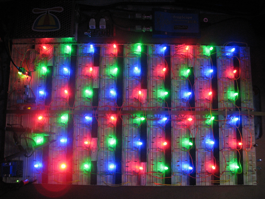
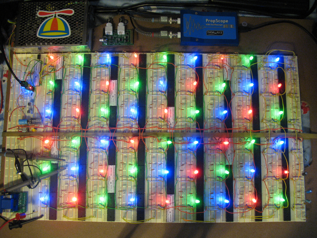
I like having 1,620 I/O at my fingertips.
To study the nature of randomness in a digital processor network using the same clock source, 54 prop chips were all connected to a master prop.
The master prop holds the eeprom, and accepts prop plug input for memory/program download.
The master prop controls the reset and clock lines for all 54 props.
The master prop also sends all combinations of a word out broadcast to all 54 props that are connected bus network style.
When a slave prop sees its number broadcast on the bus line, it replys with the same number.
Then the slave prop runs code depending on the number broadcast.
Its possible to broadcast messages to all props, or single props, after the initial enumeration is done.
Repeats are possible in any system that has reduced choices and increased speeds.
If repeats are a worry, then a long sized variable should be used in the random ID generation.
Enumeration of the Randomly generated ID's

Every step up in variable size reduces the speed that the whole system can communicate at due to more data being sent over the same speed pipe.
The communicaiton speeds of the bus network can be increased with lower value resistors, but the power draw will increase, if the props are connected to the bus with lower values, one needs to adjust all other bus resistors in relation.
Having?
You take 55 props,
some programming, (attached)
a bag of 470 ohm resistors(500) (not attached)
a 3.3v regulator (2A)
a huge breadboard
wire
57 leds
A prop scope is shown in the picture, which works well on DIAGNOSTICS.
(there are sharks in the water here, no swimming without a propscope on your boat.)
432 cores, 1,620 I/O, 64.8 A max peak draw - 10.8A continuous, @3.3v.
150kbps - communications using the same rx/tx lines for programming all 54 props.
Word location enumeration of 54 randomly generated ID's
****************END TRANSMISSION**************
TERMS OF USE: MIT License & Licensed under the TAPR Open Hardware License (www.tapr.org/OHL)
"Permission is hereby granted, free of charge, to any pers...........................
..............................OMITTED FOR FORUM............................................. ..
.................. OF OR IN CONNECTION WITH THE SOFTWARE OR THE USE OR OTHER DEALINGS IN THE SOFTWARE. "
The dsp/fpga king is dead, long live the prop.
BigBoy55jpg.pdf
4884 - Archive [Date 2010.12.16 Time 04.33].zip
Articulating Boiler - Archive [Date 2010.12.16 Time 04.34].zip
BigBoy55.pdf<---skeeeeematik
BigBoy55litjpg.pdf
I like having 1,620 I/O at my fingertips.
To study the nature of randomness in a digital processor network using the same clock source, 54 prop chips were all connected to a master prop.
The master prop holds the eeprom, and accepts prop plug input for memory/program download.
The master prop controls the reset and clock lines for all 54 props.
The master prop also sends all combinations of a word out broadcast to all 54 props that are connected bus network style.
When a slave prop sees its number broadcast on the bus line, it replys with the same number.
Then the slave prop runs code depending on the number broadcast.
Its possible to broadcast messages to all props, or single props, after the initial enumeration is done.
Repeats are possible in any system that has reduced choices and increased speeds.
If repeats are a worry, then a long sized variable should be used in the random ID generation.
Enumeration of the Randomly generated ID's
Every step up in variable size reduces the speed that the whole system can communicate at due to more data being sent over the same speed pipe.
The communicaiton speeds of the bus network can be increased with lower value resistors, but the power draw will increase, if the props are connected to the bus with lower values, one needs to adjust all other bus resistors in relation.
Having?
You take 55 props,
some programming, (attached)
a bag of 470 ohm resistors(500) (not attached)
a 3.3v regulator (2A)
a huge breadboard
wire
57 leds
A prop scope is shown in the picture, which works well on DIAGNOSTICS.
(there are sharks in the water here, no swimming without a propscope on your boat.)
432 cores, 1,620 I/O, 64.8 A max peak draw - 10.8A continuous, @3.3v.
150kbps - communications using the same rx/tx lines for programming all 54 props.
Word location enumeration of 54 randomly generated ID's
****************END TRANSMISSION**************
TERMS OF USE: MIT License & Licensed under the TAPR Open Hardware License (www.tapr.org/OHL)
"Permission is hereby granted, free of charge, to any pers...........................
..............................OMITTED FOR FORUM............................................. ..
.................. OF OR IN CONNECTION WITH THE SOFTWARE OR THE USE OR OTHER DEALINGS IN THE SOFTWARE. "
The dsp/fpga king is dead, long live the prop.


Comments
Uses:
-Particle and Planet simulations.
-Spread spectrum data broadcast.
Multi-frequency networks, having perturbations on a base set of frequency ranges, your broadcast frequencies becomes your unique ID(or channel)
Multipin output allows huge DB broadcast levels, make sure you know what your doing if your doing this.
-PWM outputs of many AMPERE at very high frequencies. (motor control, transformer, broadcast, etc)
I have a side question, you posted animated gif's of the propscope and serial terminal what software tool did you use
to capture and create them. It is a slick way to show propscope captures instead of trying to record it using a video camera.
Thank's
Tom
I don't understand this part: Is this a theoretical max?
10.8A works out to be 196mA per Prop. This seems like a lot of current. I'm I missing something?
I keep wanting to try something like this. I keep trying to think of a problem a bunch of Props working together could solve. Make that a problem I care about. Most of my ideas so far deal with image processing (both input and output).
Thanks for sharing.
Duane
Edit: I see now. It's the current this many Props are capable of sourcing (and I suppose sinking).
Nice job on this project.
Will preface this by saying that I have not yet moved up to the Propeller, so I don't know any spin.
What method are you using to truly generate the random numbers?
To me, the only way of getting a set of well-distributed random numbers is to use some external input.
Thanks.
W
This object generates real random numbers by stimulating and tracking CTR PLL jitter. It requires one cog and at least 20MHz.
http://obex.parallax.com/objects/62/
It basically said,
You need to run my enumeration sequence initially to get each prop unique.
(i see no way to do this without the initial random ID enumeration, due to the broadcast nature of this design)
Then you can re-number the ID's of each prop using the initial enumerations unique ID's.
IF you need any props to retain their ID's after power off, the prop would need pins as ID's or external inputs(eeproms, etc)
If you need individual props to be specific ID's (due to unique pin function) then it would be wise to install a eeprom or pin ID on that one/many prop, and have all other props acquire the ID from enumeration. (any prop with ID 0 would acquire enumeration ID.)
It would use 2 pins from each prop to do the enumeration, but it would get you the permanent numbering you are looking for without having to manage 55 eeproms.
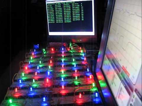
BTW, ClockLoop. This is REAL fantastic, but your video doesn't really show of any synchronizing. How about putting an RGB LED on each prop and playing a little animation across all 55?
Ok. It will take me a bit to hook it up.
-Phil
With the big Brain, to keep track of all those wires, I take photos each time before moving. Then when reassembling after the move, the photo is the only reference needed especially if some errant wire was bumped off.
The photo at the link shows how many wires need to be tracked for a Propeller Brain with 100+ chips.
http://1.bp.blogspot.com/-_cQ2cAJvkGM/Tu2OqcbuQYI/AAAAAAAAADc/v5PoM2wzpD4/s1600/wiring.jpg
Oh no! Sorry to hear about the loss...those 9-volt batteries that have close +/- terminals on the end can do damage to components in the same bag. Tape over the ends seems to work for me. How do you test each propeller chip to know its bad? Do they work partially with some pins or are they completely dead and won't run code?
Perhaps you can still get some use from each chip based on partial functioning. I also wonder why the props were pulled from the boards... I find the boards to be an excellent way to keep the lot protected and for transport, wrapping the boards in a layer of anti-static material and following with a packing of soft cotton towels, then stacked with more boards seems to work.
Some of these boards have metal backing and weigh more when shipping, however the high density ones have light weight transparent backing made from recycled clipboards. You can see the arrangement here where the boards (one board to the next) are waiting for disconnection (wires between the large boards) and packing and shipping (green backing is visible).
The Earthquake Protection with the Coddler link describes the Coddler for solderless breadboards. As an experiment some Coddlers were shipped but not with the breadboards. The polymer cracked and was replaced. Here is what it looks like reassembled.
"then it is a mere question of time when men will succeed in attaching their machinery to the very wheel-work of nature." Nikola Tesla
And now I reveal the point of designing this huge propeller grid.
A.C.S.E.R. Structure complete, wiring/soldering/programming up next.
Dec 21st 2012, target completion date, confirmed.
Initiate phase 2: soldering minimal antenna and firmware design for hydrogen resonance test.
This initial design will require a minimum of 42 propeller chips, with a desired target of 84 chips.
After tests with 84 chips, the next step up is to install and wire the maximum # of 504 prop chips.
Yes, the final design will require 504 propeller chips. = $4,000
Once the inital 42 chips are soldered and the system is working, and I have a running program, I will start a new thread in projects outlining the details of this device, its capabilities, tests, methods, schematics, pcb design files, spin programs, and more detailed video and images.
The most important part of documentation will be the success or failure of this device to actually do what I intend it to do. Its (very likely)possible that other uses will be found as I start to test with it.
Images show proper placement of propeller chips on one of the star like links in the frame.
These are only installed at centers of all 3 axis.
http://www.onbeing.org/program/uncovering-codes-reality/feature/symbols-power-adinkras-and-nature-reality/1460
A.C.S.E.R. --
A.tomic
C.reation through
S.ynchronized
E.mission of
R.adiation
Doubly-even self-dual linear binary error-correcting block code physics adinkra.
HACK THE PLANET!
This is the future, and its up to YOU to get it going, I am NOT going to sell these. I also cannot do all the work by myself. (actually i can, but what fun is that?)
I am being attacked by covert sources, but don't believe me, believe the search warrants.
(of course they want to destroy someone that presents the possibility of eliminating all old world hierarchical controlled resource limits.)
Even financial oppression, cannot stop me. I'll use magnet wire on this thing, by hand, without a microscope, I don't care, BRING IT.
And just to show off, I'll build the frame using a kids toy, K'NEX.
(instead of using flexpcbs, optical interconnects, custom designed frame and all that fancy jazz)
And if you STILL don't think that this amounts to anything, then let me ask you this.
Can energy have structure?
.
.
.
So then why is creating structure through synchronized energy(a.k.a. structurized energy) such a foreign concept to you?
I swear, trying to teach simple concepts to brainwashed(government controlled school curriculum, duh?) masses is harder than crystallized carbon.
What does it do? Or what will it do once it's up and running?
Thank you mike for getting back to me. I apologies to everyone for the sailor talk.
The black things in between each propeller chip and what the object this video is constructed out of, are k'nex plastic parts that snap together.
I made an entire frame out of them to hold the pcb's, as also shown in the videos.
http://www.knex.com/Educators/
Feel free to start using them in your own ideas and projects, they are very useful, and easy to attach pcb's and wire up projects with stability and cheap price.
The use of k'nex in the frame is just because I can't afford a 3d printer, or to have someone mill me parts.
I suppose I could have made it all out of cardboard, and duct tape.
The frame measurements were taken and pcb's were custom ordered to fit in the frame.
Magnet wire was used because of its thin size, availability to me. Wire wrap could also be used.
The circuit used in this design is exactly the same as the first post in the design(except it has a different number of them)
In the 3d image above(the one with the colorful box, if you find the "Processor Axis" you will see all 3 axis in all directions.)
The processors are also along axis surrounding the object, to connect to the outer pcb's.
The reason the video doesn't show all of these processors is because as mentioned above, thousands of dollars are required, which I currently don't have.
THIS OBJECT IS.....
A.C.S.E.R. --
A.tomic
C.reation through
S.ynchronized
E.mission of
R.adiation
I'm going to repeat it so you don't quickly skim over it.
Make sure you read it slowly and, believe the hype.
A.C.S.E.R. --
A.tomic
C.reation through
S.ynchronized
E.mission of
R.adiation
A.C.S.E.R. --
A.tomic
C.reation through
S.ynchronized
E.mission of
R.adiation
A.C.S.E.R. --
A.tomic
C.reation through
S.ynchronized
E.mission of
R.adiation
Or not, believe what you want.
Do you think Benjamin Franklin knew exactly what he was doing, when he was doing it?
Probably not, but he had a pretty good idea, right? (probably not, too)
By no means am I a Benjamin Franklin, I have consumed too much fluoride and chlorine against my will in my city water that i cannot afford to remove, arsenic in my chicken, and bpa in almost every food/drink packaged in plastic, not to mention bpa on almost every reciept you touch at a store. My brain does not function like his on farm fresh raised food, and nutritious well water, sorry. I am trying my best, with what I have been given in this life.
I wasn't quite sure if the idea was to measure hydrogen resonance or calculate it... I made a 1 gauss digital magnet just to cover the bases.... thinking that if he was going to measure the resonance, it might be good to rotate the entire apparatus... making the measurement 3d.
now... about that hydrogen resonance. I'm interested.... lets get this thread going again!
Loopy... exactly what did you have in mind?