

Need HELP - We want to make the reversal counter
 arktur
Posts: 31
arktur
Posts: 31
Dear Sirs!
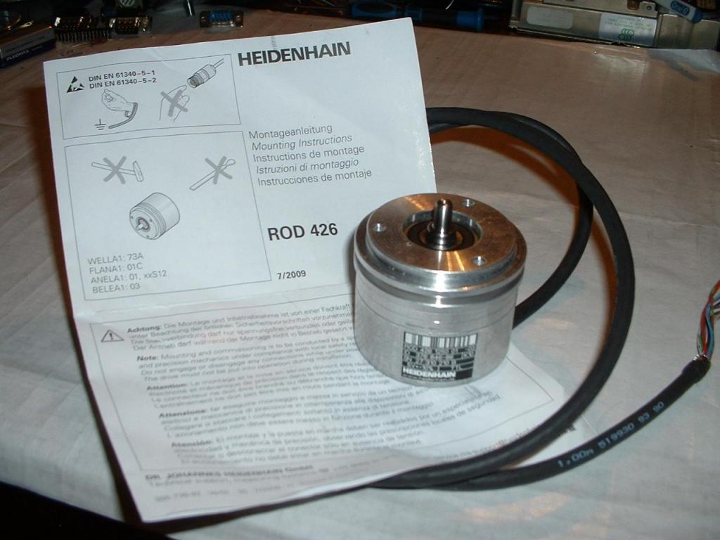
We want to make the reversal counter for calculation of pulses from
HEIDENHAIN Encoder 426 , Model 1250 pulses, OUT - TTl, 5V.
http://iseepdf.com/preview/aHR0cDovL3d3dzgudGZlLnVtdS5zZS9mb3Jza25pbmcvQ29udHJvbF9TeXN0ZW1zL0NvdXJzZXMvREJUL01vdGlvbl9Db250cm9sL0hlaWRlbmhhaW4lMjAtJTIwUm90YXJ5JTIwRW5jb2RlcnMlMjAoZXhjZXJwdCkucGRm
For the visual control we want to use the indicator 2x16 RAYSTAR
RC1602E-YKY-CSX (is made on a basis Hitachi 44780 controller IC).
http://www.microchip.ua/LCD/Raystar/pdf/RC1602E.pdf
In the INTERNET we have found the information on production to PARALLAX.
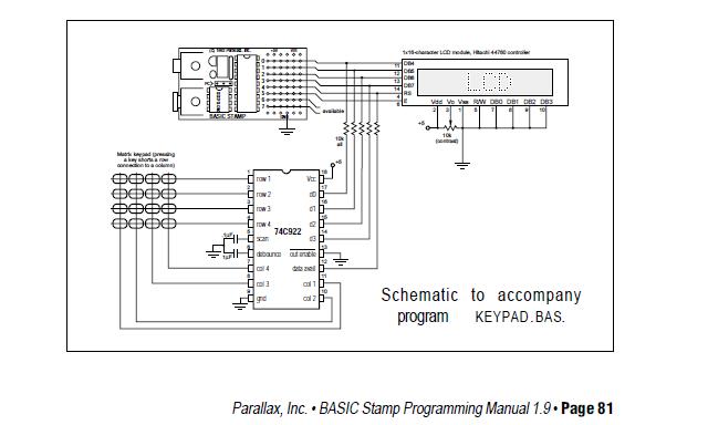
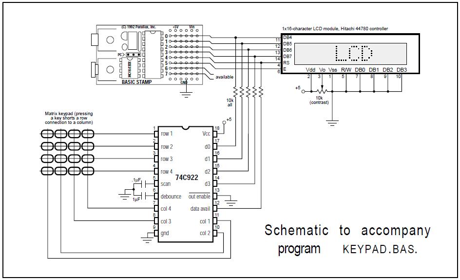
In the description BS1-appnotes.pdf we have found ways of connection
BS-1 with LCD Hitachi 44780, Keypad, Servo and other variants.
We have decided(solved), that for the decision of our task quite will
consult(cope) BS-1 or BS-2.
http://www.parallax.com/Portals/0/Downloads/appnt/stamps/bs1appnotes.pdf
We have bought BASIC Stamp 1 Module, BASIC Stamp 2 Module, Super
Carrier Board, BASIC Stamp 1 Serial Adapter, the indicator 16x2
RAYSTAR RC1602E-YKY-CSX, HEIDENHAIN Encoder 426 1250, Model 1250
pulses, OUT - TTl, 5V.
http://www.parallax.com/Store/Microcontrollers/BASICStampModules/tabid/134/CategoryID/12/List/0/SortField/0/Level/a/ProductID/3/Default.aspx
http://www.parallax.com/Store/Microcontrollers/BASICStampModules/tabid/134/CategoryID/12/List/0/SortField/0/Level/a/ProductID/1/Default.aspx
http://www.parallax.com/Store/Microcontrollers/BASICStampModules/tabid/134/CategoryID/12/List/0/SortField/0/Level/a/ProductID/44/Default.aspx
http://www.parallax.com/Store/Microcontrollers/BASICStampDevelopmentBoards/tabid/137/CategoryID/12/List/0/SortField/0/Level/a/ProductID/122/Default.aspx
http://www.parallax.com/tabid/441/Default.aspx
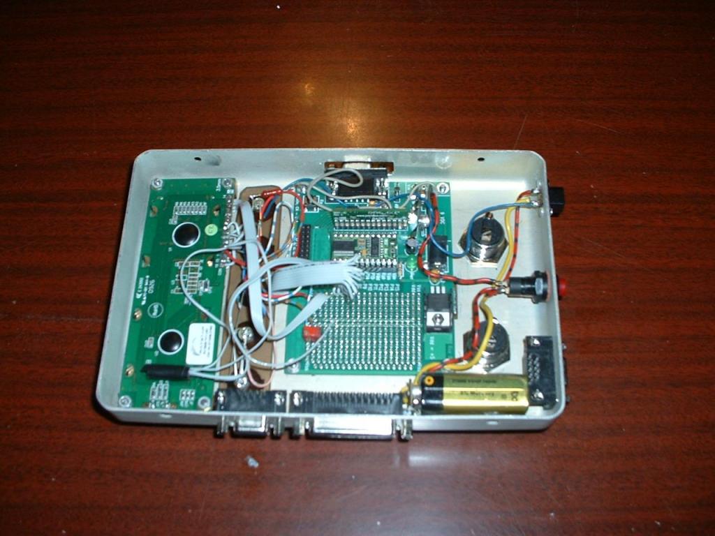
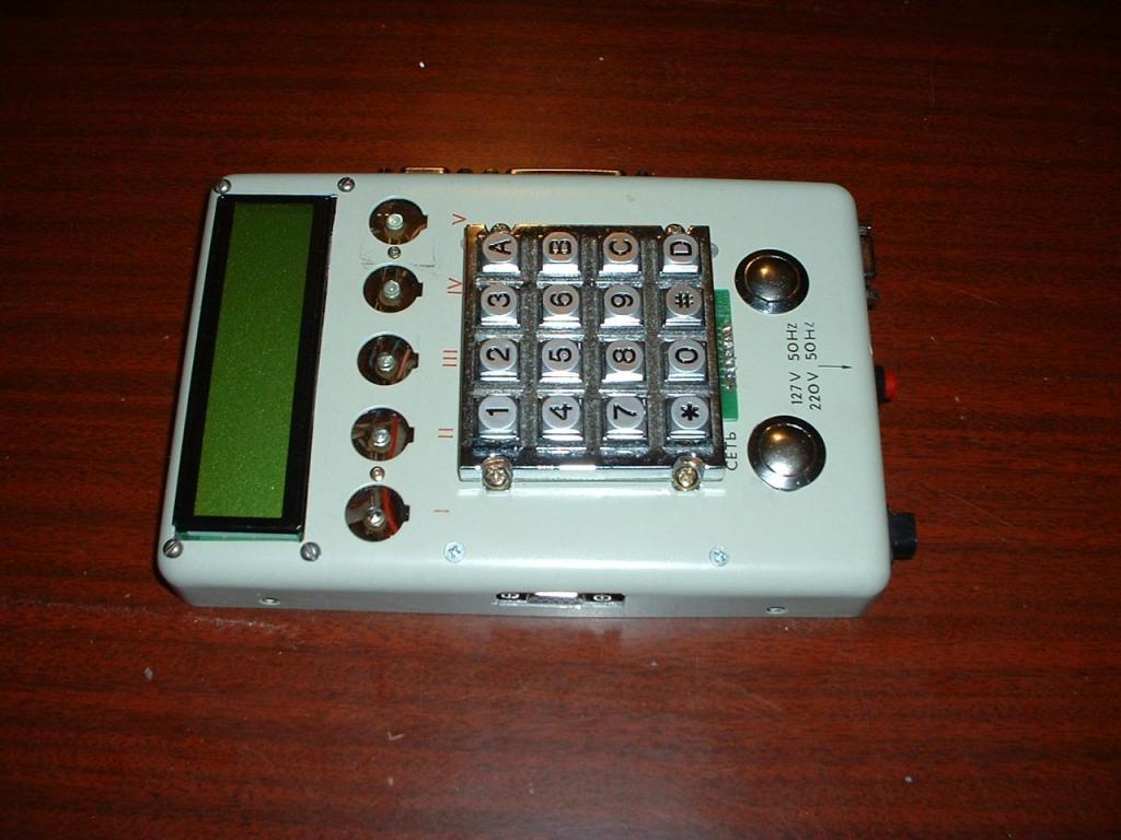
Have collected in a box.
Have loaded BASIC Stamp Windows Editor v2.5 (R2) - (Supports Windows
2K/XP/Vista/7) Includes software, USB driver, example code and help
for all BASIC Stamp modules.
Have invited the Programmer Man. When he has seen, has said, that
BASIC Stamp 1 Module, BASIC Stamp 2 Module it is impossible to program
on job with 16x2 RAYSTAR RC1602E-YKY-CSX (is made on a basis Hitachi
44780 controller IC)!!!
Whether correctly to us has said of the Programmer Man?
Really we can not decide(solve) on these elements a simple task: to
make the reversal counter for calculation of pulses from HEIDENHAIN
Encoder 426 1250, Model 1250 pulses, OUT - TTl, 5V.., For the visual
control we to use the indicator 16x2 RAYSTAR RC1602E-YKY-CSX (is made
on a basis Hitachi 44780 controller IC).
Have switched on the counter, have reset in "0"
1. We rotate HEIDENHAIN Encoder to the right - counter summarizes
pulses and shows us on the indicator of number, which are increased.
2. We rotate HEIDENHAIN Encoder to the left - counter subtracts pulses
and shows us on the indicator of number, which decrease.
Please explain Whether we can collect and program the reversal counter
from elements, available at us?
How is correct to us to connect BASIC Stamp 1 Module (or BASIC Stamp 2
Module) Super Carrier Board, the indicator 16x2 RAYSTAR
RC1602E-YKY-CSX, HEIDENHAIN Encoder 426 1250, Model 1250 pulses, OUT -
TTl, 5V?
How correctly to make the program and to write down her(it) in BASIC
Stamp 1 Module (or BASIC Stamp 2 Module)?


We want to make the reversal counter for calculation of pulses from
HEIDENHAIN Encoder 426 , Model 1250 pulses, OUT - TTl, 5V.
http://iseepdf.com/preview/aHR0cDovL3d3dzgudGZlLnVtdS5zZS9mb3Jza25pbmcvQ29udHJvbF9TeXN0ZW1zL0NvdXJzZXMvREJUL01vdGlvbl9Db250cm9sL0hlaWRlbmhhaW4lMjAtJTIwUm90YXJ5JTIwRW5jb2RlcnMlMjAoZXhjZXJwdCkucGRm
For the visual control we want to use the indicator 2x16 RAYSTAR
RC1602E-YKY-CSX (is made on a basis Hitachi 44780 controller IC).
http://www.microchip.ua/LCD/Raystar/pdf/RC1602E.pdf
In the INTERNET we have found the information on production to PARALLAX.
In the description BS1-appnotes.pdf we have found ways of connection
BS-1 with LCD Hitachi 44780, Keypad, Servo and other variants.
We have decided(solved), that for the decision of our task quite will
consult(cope) BS-1 or BS-2.
http://www.parallax.com/Portals/0/Downloads/appnt/stamps/bs1appnotes.pdf
We have bought BASIC Stamp 1 Module, BASIC Stamp 2 Module, Super
Carrier Board, BASIC Stamp 1 Serial Adapter, the indicator 16x2
RAYSTAR RC1602E-YKY-CSX, HEIDENHAIN Encoder 426 1250, Model 1250
pulses, OUT - TTl, 5V.
http://www.parallax.com/Store/Microcontrollers/BASICStampModules/tabid/134/CategoryID/12/List/0/SortField/0/Level/a/ProductID/3/Default.aspx
http://www.parallax.com/Store/Microcontrollers/BASICStampModules/tabid/134/CategoryID/12/List/0/SortField/0/Level/a/ProductID/1/Default.aspx
http://www.parallax.com/Store/Microcontrollers/BASICStampModules/tabid/134/CategoryID/12/List/0/SortField/0/Level/a/ProductID/44/Default.aspx
http://www.parallax.com/Store/Microcontrollers/BASICStampDevelopmentBoards/tabid/137/CategoryID/12/List/0/SortField/0/Level/a/ProductID/122/Default.aspx
http://www.parallax.com/tabid/441/Default.aspx
Have collected in a box.
Have loaded BASIC Stamp Windows Editor v2.5 (R2) - (Supports Windows
2K/XP/Vista/7) Includes software, USB driver, example code and help
for all BASIC Stamp modules.
Have invited the Programmer Man. When he has seen, has said, that
BASIC Stamp 1 Module, BASIC Stamp 2 Module it is impossible to program
on job with 16x2 RAYSTAR RC1602E-YKY-CSX (is made on a basis Hitachi
44780 controller IC)!!!
Whether correctly to us has said of the Programmer Man?
Really we can not decide(solve) on these elements a simple task: to
make the reversal counter for calculation of pulses from HEIDENHAIN
Encoder 426 1250, Model 1250 pulses, OUT - TTl, 5V.., For the visual
control we to use the indicator 16x2 RAYSTAR RC1602E-YKY-CSX (is made
on a basis Hitachi 44780 controller IC).
Have switched on the counter, have reset in "0"
1. We rotate HEIDENHAIN Encoder to the right - counter summarizes
pulses and shows us on the indicator of number, which are increased.
2. We rotate HEIDENHAIN Encoder to the left - counter subtracts pulses
and shows us on the indicator of number, which decrease.
Please explain Whether we can collect and program the reversal counter
from elements, available at us?
How is correct to us to connect BASIC Stamp 1 Module (or BASIC Stamp 2
Module) Super Carrier Board, the indicator 16x2 RAYSTAR
RC1602E-YKY-CSX, HEIDENHAIN Encoder 426 1250, Model 1250 pulses, OUT -
TTl, 5V?
How correctly to make the program and to write down her(it) in BASIC
Stamp 1 Module (or BASIC Stamp 2 Module)?
1024 x 768 - 97K
1024 x 768 - 86K
640 x 384 - 31K
944 x 574 - 69K

550 x 320 - 5K
1024 x 768 - 80K
Comments
'
I thought I read into your problem, But you have a jpeg of it on you post? confused!
'
Not really sure what your after????
The Programmer Man does not believe you can use the RAYSTAR LCD display along with BS1 or BS2, right?
This is what you want the Basic Stamp to do but so far haven't figured out how, right?
I read questions from other people. I see, what not I have made one such mistake. Probably the indicator 16x2
RAYSTAR RC1602E-YKY-CSX will not work with BS-1 or BS-2. But it not a problem. Instead of RAYSTAR RC1602E-YKY-CSX I can use KW4-561ASB.
http://www.redpower.com.tw/pdf/FOUR%20DIGIT%20DISPLAY/KW4-561ASB.doc
There is a question:
How is correct to us to connect BASIC Stamp 1 Module (or BASIC Stamp 2
Module) Super Carrier Board, the indicator KW4-561ASB (4x7), HEIDENHAIN Encoder 426 1250, Model 1250 pulses, OUT -
TTl, 5V?
Have switched on the counter, have reset in "0"
1. We rotate HEIDENHAIN Encoder to the right - counter summarizes
pulses and shows us on the indicator of number, which are increased.
2. We rotate HEIDENHAIN Encoder to the left - counter subtracts pulses
and shows us on the indicator of number, which decrease.
Please explain Whether we can collect and program the reversal counter
from elements, available at us?
We can replace the indicator 2x16 RAYSTAR RC1602E-YKY-CSX (is made on a basis Hitachi 44780 controller IC) on 7-segment LED displays. On Page 67 · StampWorks we have found EXPERIMENT *10: A DIGITAL CLOCK. There are used 4 DIGIT x 7-segment LED displays. It approaches me, but it is necessary to add a POINT and to make the counter reversal. Here for calculation the pulse from PULSE GENERATOR is used which comes on contact 15. And I need to make so: if the pulse "A" comes by first, and the pulse "B" by second (left rotation) - then goes summation and the indication on the display is increased; If the pulse "B" comes by first, and pulse "A" by second (right rotation), then the indications on the display should decrease. A pulse "A" we can connect on contact 15, then on what contact to connect a pulse "B"?
It is necessary to apply not below BS-2.
Now at us the basic problem that we want to compel BS-2 to decide(solve) by the program a direction of calculation of pulses "+" or "-".
BS-2 Itself should define(determine) in what direction turns ROD-426 and to accept the decision to add (+) or to take away (-)?
Thus we want to use only two signals "A" and "B".
Similar that nobody wants or can not help me.
I have found the program and I managed to connect the indicator 2x16 RAYSTAR
RC1602E-YKY-CSX (is made on a basis Hitachi 44780 controller IC) under BS-2.
The indicator works normally. One problem is decided(solved).
The Programmer Man can not write the program for definition of a direction
Rotations HEIDENHAIN Encoder 426 1250, Model 1250 pulses, OUT - TTl, 5V.
I have applied the circuit decision on microcircuits (decoder). She works simply.
If Encoder rotates to the right, the pulses go only on the channel "A", and the channel "B" has a constantly low level.
If Encoder rotates to the left, the pulses go only on the channel "B", and the channel "A" has a low level.
The second problem is decided(solved).
There was one problem - to write the program of the counter.
We want to connect two HEIDENHAIN Encoder 426 1250, Model 1250 pulses, OUT - TTl, 5V.
Everyone Encoder should work independently.
The Encoders are connected to BS-2 so:
E1 "A" - pin 13 BS-2
E1 "B" - pin 14 BS-2
E2 "A" - pin 10 BS-2
E2 "B" - pin 11 BS-2
One pulse corresponds(meets) 0,01 mm.
The indication about a condition owes first Encoder (E1) is deduced in the top line, and
The indication about a condition second Encoder (E2) should be deduced(removed) on the bottom line on the indicator 2x16 RAYSTAR
RC1602E-YKY-CSX (is made on a basis Hitachi 44780 controller IC) under BS-2.
I.e. the indication should be in a format:
Encoder1_00,00mm
Encoder2_00,00mm
The digital indication should vary according to changes of a rule(situation) any Encoders and specify true meaning(importance).
Can someone help me to write this program???
Bs-2 - lcd
In such kind I want to receive indication from encoders.
(1piece), Super Carrier Board (1 piece), BASIC Stamp 1 Serial Adapter
(1 piece), the indicator 16x2
RAYSTAR RC1602E-YKY-CSX (1 piece), HEIDENHAIN Encoder 426 1250, Model 1250
pulses, OUT - TTL, 5V (2 pieces).
I would like to make the monitoring system the Luft in the Reducer.I
would like to make the reversal two-channel counter.
I want to construct the counter itself on BS-2 basis.
The indication should be shown on LCD 2x16.
To the first channel of the counter the pulses go from ENCODER1
(quantity(amount) of rotation of the shaft of the motor counted in
millimeters 1250 pulses = 1250 mm).
To the second channel of the counter the pulses go from ENCODER2
(quantity(amount) of rotation of the leaving shaft of a reducer
counted in millimeters 1250 pulses = 1250 millimeters)
Four digits should be shown on the indicator.
In the complete version BS-2 should define(determine) a difference
between the indications of the first and second counter (it will be
the Luft in the Reducer).
If The LUFT will be more of a given size (for example more than 1 mm,
i.e. there are more than 100 pulses) then BS-2 should write on
indication a word "ALARM", show digital meaning(importance) The LUFT
and a signal,
for example on PIN15 - HIGH.
We will connect this signal (with PIN15) to the electrical circuit of
the motor operation.
The programmer man was not able to program DERODER in BS-2.
Therefore we have made DECODER1 and DECODER2 on logic elements (on
microcircuits).
These DECODERS give out only signals "+" at positive rotation and only
signals "-" at negative rotation ENCODERS.
We have made the device on BS-2. ENCODER1 and ENCODER2 are connected
on DECODER1 and DECODER2.
The output of DECODER1 is connected on P13 and P14 BS-2, and outputs
DECODER2 are connected on P10 and P11 BS-2.
The programmer man was not able to program BS-2 under this scheme either.
Then we removed ENCODER2 and DECODER2.
The programmer man was not able to program BS-2 this time either.
Then we replaced LCD 2x16 for LED 4x7
Even this time the programmer man was not able to program BS-2.
For LED 4x7 I have connected so:
P0 - A
P1 - B
P2 - C
P3 - D
P4 - E
P5 - F
P6 - G
P7 - DP
P8 - DIGIT0
P9 - DIGIT1
P10 - DIGIT2
P11 - DIGIT3
P13 - ENCODER A
P14 - ENCODER B
P12;P15 - ARE FREE
For LCD 2x16 (RAYSTAR - analog HITACHI 44780) I have connected so:
P0 - E
P2 - RW
P3 - RS
P4 - D4
P5 - D5
P6 - D6
P7 - D7
P10 - ENCODER2- A
P11 - ENCODER2- B
P13 - ENCODER1- A
P14 - ENCODER1- B
P1;P8;P9;P12;P15 - ARE FREE
Can someone help is correct to write the program under any variant?
P.S. Probably Someone at one time applied joint job of two modules?
Ours The programmer man has offered to try joint job BS-1 and BS-2.
He wants to try commands SERIN; SERIN_SEROUT.
DECODER Module - will accept pulses from ECODER. DECODER Module will
define(determine) a direction and to form pulses "+A" for positive
calculation OR pulses " - B " for negative calculation.
BS-2 Will carry out ONLY function of the reversal counter. On his
input Pin13 the positive pulses "+A" will act,
And on an input Pin14 the negative pulses "-B" will act. BS-2 should
only count up (to accumulate or to subtract) these pulses and to send
result on BS-1
BS-1 Should accept the information from BS-2. He will prepare this
information under a format for LCD and to give her on HD44780.
Can we raise(increase) an overall performance of our device?
I shall be very grateful for your remarks.
I think you are asking about increasing the throughput speed, or baud rate. I too have connected both BASIC Stamp ones and twos. When using the BS1, cap the baud rate to 1200 serially. The BS2 can sync with the BS1 at 1200. It you put the display on the BS2, it can also work well at 1200 baud. If a separate line is used, 9600 is workable. I use a serial display but yours looks parallel. There is much information about connecting parallel if you need it. In reviewing your documents I think you have that aspect working.
The BASIC Stamp Supercomputer and others have different Stamp versions connected. Here are some links.
- SEED Stamp Supercomputer (Self Evolving Enumerating Deterministic)
- BSS Basic Stamp Supercomputer
- TCS TriCore Stamp Supercomputer
- MSS Minuscule Stamp Supercomputer
- TSS Tiny Stamp Supercomputer
- M.O.M. Master Offloader Machine
So did you get it to count pulses for the Heidenhain?Dear Humanoido!
For joint job BS-1 and BS-2 we use commands(team) SERIN; SERIN_SEROUT.
We have received positive result.
BS-1 and BS-2 - CAN WORK TOGETHER!
Now I temporarily have disconnected BS-1 and LCD 2x16 HD44780.
Now at me (temporarily) BS-2 and LED 4x7.
For LED 4x7 I have connected so:
P0 - A
P1 - B
P2 - C
P3 - D
P4 - E
P5 - F
P6 - G
P7 - DP
P8 - DIGIT0
P9 - DIGIT1
P10 - DIGIT2
P11 - DIGIT3
P13 - DECODER B -
P14 - DECODER A +
P12; P15 - ARE FREE
I have reduced speed of rotation HEIDENHAIN Encoder 426.
The pulses from HEIDENHAIN Encoder 426 are connected on the logic circuit DECODER.
DECODER decodes pulses and sends them on BS-2.
If the left rotation ENCODER - then P14 - DECODER A +
If the right rotation ENCODER - then P13 - DECODER B -
I can not correctly consider(count) pulses.
Now (temporarily) I have taken a sample of the program "CLOCK" and has changed a little.
Such program has turned out:
++++
' {$STAMP BS2}
' {$PBASIC 2.5}
'
[Program Description]
'
' This program takes an external 1 Hz signal from the pulse generator and
' synthesizes a simple clock/timer. This code will run, unmodified, on and
' BS2-family module.
'
[I/O Definitions]
Segs VAR OUTL ' Segments on P0 - P7
Digs VAR OUTC ' Digit control pins
Tic PIN 14 ' input pulses DECODER A +
'
[Constants]
Blank CON %00000000 ' all segments off
DecPnt CON %10000000 ' decimal point on
IsHigh CON 1
IsLow CON 0
'
[Variables]
nTic VAR Bit ' new tic input
oTic VAR Bit ' old tic value
xTic VAR Bit ' change (1 when 0 - > 1)
secs VAR Word ' seconds
time VAR Word ' formatted time
theDig VAR Nib ' current display digit
'
[EEPROM Data]
' .GFEDCBA
'
Digit0 DATA %00111111 ' digit patterns
Digit1 DATA %00000110
Digit2 DATA %01011011
Digit3 DATA %01001111
Digit4 DATA %01100110
Digit5 DATA %01101101
Digit6 DATA %01111101
Digit7 DATA %00000111
Digit8 DATA %01111111
Digit9 DATA %01100111
DigSel DATA %1110 ' digit 0 active
DATA %1101 ' digit 1 active
DATA %1011 ' digit 2 active
DATA %0111 ' digit 3 active
'
[Initialization]
Reset:
Digs = %1111 ' all off
DIRS = $0FFF ' make segs and digs outputs
'
[Program Code]
Main:
DO WHILE (Tic = IsHigh) ' wait during high cycle
GOSUB Show_Clock
LOOP
DO WHILE (Tic = IsLow) ' wait during low cycle
GOSUB Show_Clock
LOOP
secs = secs + 1 // 10000 ' update current time
GOTO Main
'
[Subroutines]
Show_Clock:
time = (secs / 10) * 10 ' get mins, move to 10s
time = time + (secs // 10) ' add seconds in 1s/10s
Segs = Blank ' clear display
READ (DigSel + theDig), Digs ' select digit
READ (Digit0 + (time DIG theDig)), Segs ' move digit pattern to segs
IF (theDig = 2) THEN
Segs = Segs | DecPnt ' add decimal point
ENDIF
theDig = theDig + 1 // 4 ' update digit pointer
RETURN
++++
I have connected positive pulses (A +) on PIN14.
This program counts up pulses. But only summarizes.
I want has connected negative pulses (B-) on PIN13.
The program should do (make) so:
- If there come pulses (A +) on PIN14 - then they are summarized
- If there come pulses (B-) on PIN13 - then are taken away
If encoder rotates forward - then there are pulses only (A +) on PIN14.
If encoder has changed a direction and rotates back - then there are only pulses (B-) on PIN13.
To me is not necessary here " encoder programm ".
The decoding of pulses will be done (made) by (with) the circuit on logic elements.
I have connected on PIN13 and PIN14 ready pulses.
I need only to add or to take away.
Per one second there will come less than 50 pulses (from 1 up to 40 pulses per one second).
How I should change this program? She should be reversal.
I do not know as to change the program and to write down in it(her) PIN13 - DECODER B -?
I do not know as to change the program and to make reversal calculation (subtraction) of pulses PIN13 - DECODER B -?
I do not know programming. I can not itself write the program. I can only a little change the ready program.
I shall be very grateful for your remarks.
You will have to adapt the display part of the program.
You have given me a part of the program the COUNTER. But I not the programmer.
I do not know as me correctly yours the program the COUNTER to attach to my program CLOCK-TEST.
In the instruction on BS-2 I have found as to connect LED 4x7 to BS-2.
I have collected this circuit. For this circuit I have found the program CLOCK-TEST.
On PIN13 I have submitted positive pulses A "+" from DECODER MODULE (instead of clock pulses 1Hz).
I have checked up - summation and the indication in all four digits works correctly.
To reduce loading on BS-2 and to increase speed of calculation BS-2 I use DECODER MODULE.
Now BS-2 should not spend the time for definition of a direction of calculation "+" or "-".
It does(makes) DECODER MODULE.
DECODER MODULE cleans(removes) pulses on any to one of channels. It depends on a direction of rotation ENCODER.
If ENCODER has a positive direction of rotation, then DECODER MODULE gives on PIN13 BS-2
Positive pulses A "+", and negative pulses B "-" closes and on PIN14 BS-2 any pulses do not come (low).
In this case reversal counter on BS-2 should add pulses.
If ENCODER has a negative direction of rotation, then DECODER MODULE gives on PIN14 BS-2
Negative pulses B "-", and positive pulses A "+" closes and on PIN13 BS-2 any pulses do not come (low).
In this case reversal counter on BS-2 should change direction calculation of pulses - he should take away pulses.
Now I am necessary the program of the reversal counter for such circuit.
I ask to change my program CLOCK-TEST: to leave in this program that part, which does(makes) indication on LED 4x7 in that kind as she is (under the circuit of connection as I have collected) and to replace a part which is called "CLOCK" as variant which the REVERSAL COUNTER is called.
I can not itself change the program. I not the programmer. I can change by places positive pulses A "+", and the negative pulses B "-" if are necessary are coordinated by(with) a direction of rotation ENCODER and direction of calculation of pulses. But strongly change the program I can not - I am not able.
Help.
P.s. Programm clock-test
Dear Humanoido! Dear skylight! Dear stamptrol! Dear SIRS!
I not the programmer.
I can not write the program for this circuit.
Help to change the program CLOCK-TEST in the program the REVERSAL COUNTER for mine of the circuit on BS-2.
The part of the program CLOCK-TEST which works on indication on LED 4x7 should not change.
From the program CLOCK-TESTнужно to clean(remove) a part, which works as CLOCK.
Instead of a part CLOCK it is necessary to add a part the REVERSAL COUNTER.
This part should be according to my electrical circuit.
Yours faithfully, Alexandr.
You will probably need to seek out a programming consultant for hire if you cannot write programs and if large code changes are required. It is not clearly understood what you want accomplished with the BS2 Reversal Counter. If you can clarify this in a specific question and it's a small change maybe we can help. You may also try flow charting exactly what you want to change. It can help the programmer.
The only way you will learn PBASIC programming is to do it in small steps and this includes when you write your programs. I also use the examples that come with products that are on Parallax website and sites. This can help alot and go a long way.
In your program: Channel a and b of encoder go on inputs 4 and 5.
It is necessary that: Channel a and b of encoder go on Pin13 and Pin14 to BS-2.
Can in your program qwuadhicount.bs2 change so:
1. To replace " inputs 4 and 5 " on " Pin13 Pin14 "
2. The result should go on the screen of the monitor PC (command DEBUG)
Yours faithfully, Alexandr
I never programmed. I do not know ENGLISH. I do not know BASIC. I know only electrician and electronik.
I do(make) translation from Russian on English and back I by the program on the computer.
As this program translates - you see what texts I write here on a forum.
This program can translate the simple colloquial texts.
This program can not translate the complex(difficult) technical texts.
Certainly I need to study ENGLISH. I need to study BASIC.
But it is very long process, and the program is necessary for my counter to me in December of the last 2010.
Now end of January, 2011. I have the device, and the program I have no!
I yesterday have found the program of mister John Barrowman.
This program is called COUNTS.BS2.
I managed to change this program so, that she worked in my device.
My counter on BS-2 has earned. The counter adds and takes away. How I want.
I назвалэту the program COUNTS-002. BS2.
But result I can see only on the monitor mine PC (command(team) DEBUG CR, DEC prom.)
Now it is necessary in the program COUNTS-002. BS2 to add an output(exit) on LED 4x7 or LCD 2x16.
But the output(exit) should be coordinated with my electrical circuit.
I have applied so :
For LED 4x7 I have connected so:
P0 - A
P1 - B
P2 - C
P3 - D
P4 - E
P5 - F
P6 - G
P7 - DP
P8 - DIGIT0
P9 - DIGIT1
P10 - DIGIT2
P11 - DIGIT3
P13 - PULSES A+
P14 - PULSES B-
P12;P15 - ARE FREE
For LCD 2x16 (RAYSTAR - analog HITACHI 44780) I have connected so:
P0 - E
P2 - RW
P3 - RS
P4 - D4
P5 - D5
P6 - D6
P7 - D7
P13 - PULSES A+
P14 - PULSES B-
P1;P8;P9;p10;P11;P12;P15 - ARE FREE
Examples of the programs of indication, which work with my electrical circuits it is possible to see in the programs
1. CLOCK-TEST For LED 4x7
2. Parallel_ LCD_2x16 for LCD 2X16
It is necessary:
1. To take counter from the program COUNTS-002, and from the program CLOCK-TEST to take program of indication for LED 4x7 and to unit these programs so, that the program COUNTS-002-LED 4x7 has turned out
The second variant:
2. To take counter from the program COUNTS-002, and from the program Parallel_ LCD_2x16 a part of the program for LCD 2X16 and to unit them so that the program COUNTS-002-Parallel_ LCD_2x16 has turned out.
I shall have two variants of the program and I can test (to try) this device on BS-2 PARALLAX.
Beforehand is grateful.
Alexandr from UKRAINE.
Dear Sirs!
We managed to make the program.
For a basis we have taken the program COUNTS John Barrowman, Parallax Technical Support Engineer Stamp Applications: Nuts and Volts February 1998.
This program (COUNTS John Barrowman) at us did not want to work. But we have made in her some changes and have added two variants an output(exit) on indication: one variant for LED 4x7, second variant for LCD 2x16.
We have made still third variant for joint job BS-1 and BS-2. But he has turned out by slowest.
Certainly these programs can still be finished.
But you can them see in the application.
Yours faithfully, Alexandr
from UKRAINE
'
Glad to hear you have it working.
NO is not a university project.
If it will be normal to work, this project will be used in METALLURGICAL branch.
The rolling unit for manufacturing steel pipes.