

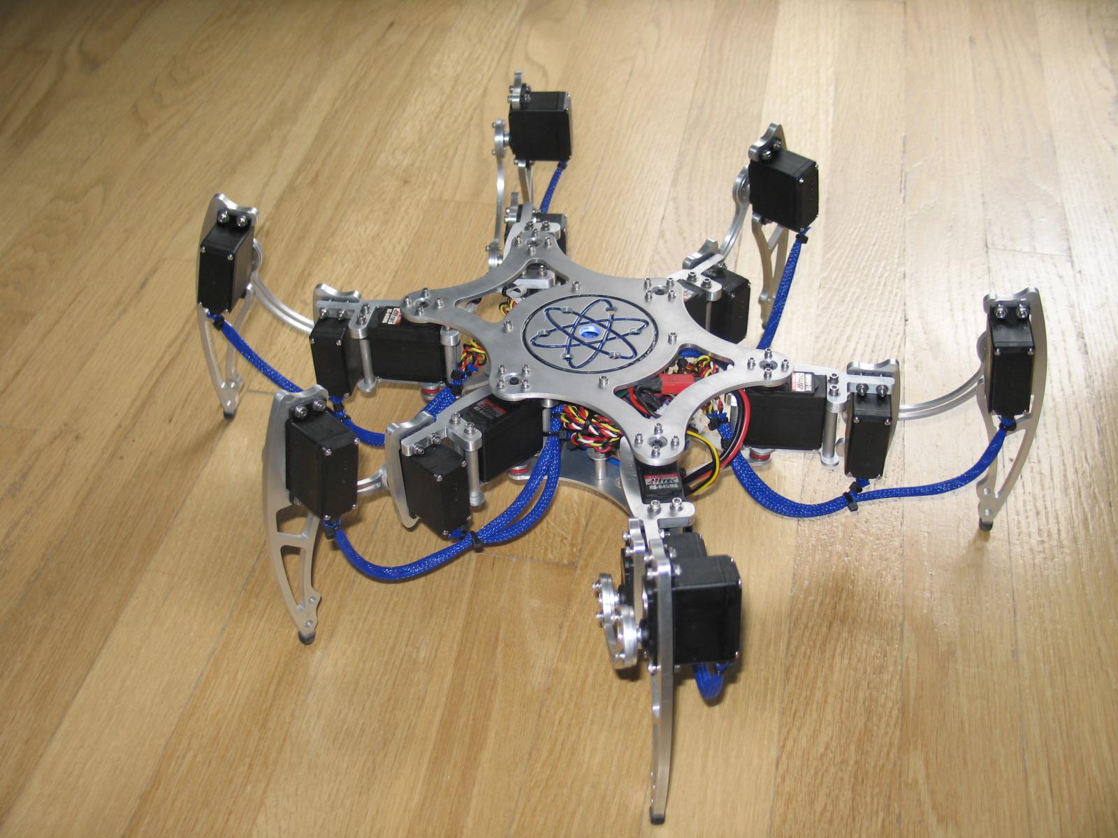
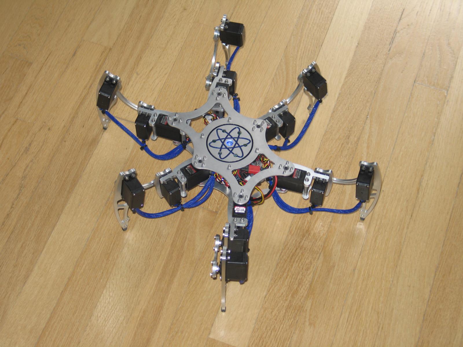
Propeller Based IK Hexapod Project

This is an on going project. But its time to post it to see how other people modify or use it.
I have ported over some code to the Propeller platform along with a lot of tweaking and with the help of several objects from the object library.
It's a software package that controls a hexapod. It can technically be modifed to run any X legged robot. Each leg has to have 3DOF.
And any size as long as you change the basic body and leg dimensions.
It's a Inverse Kinematic solution and it computes everything on the run. Currently all the math is done in spin.
I will be editing this with more details. But I have had several people interested in the code so here you go.
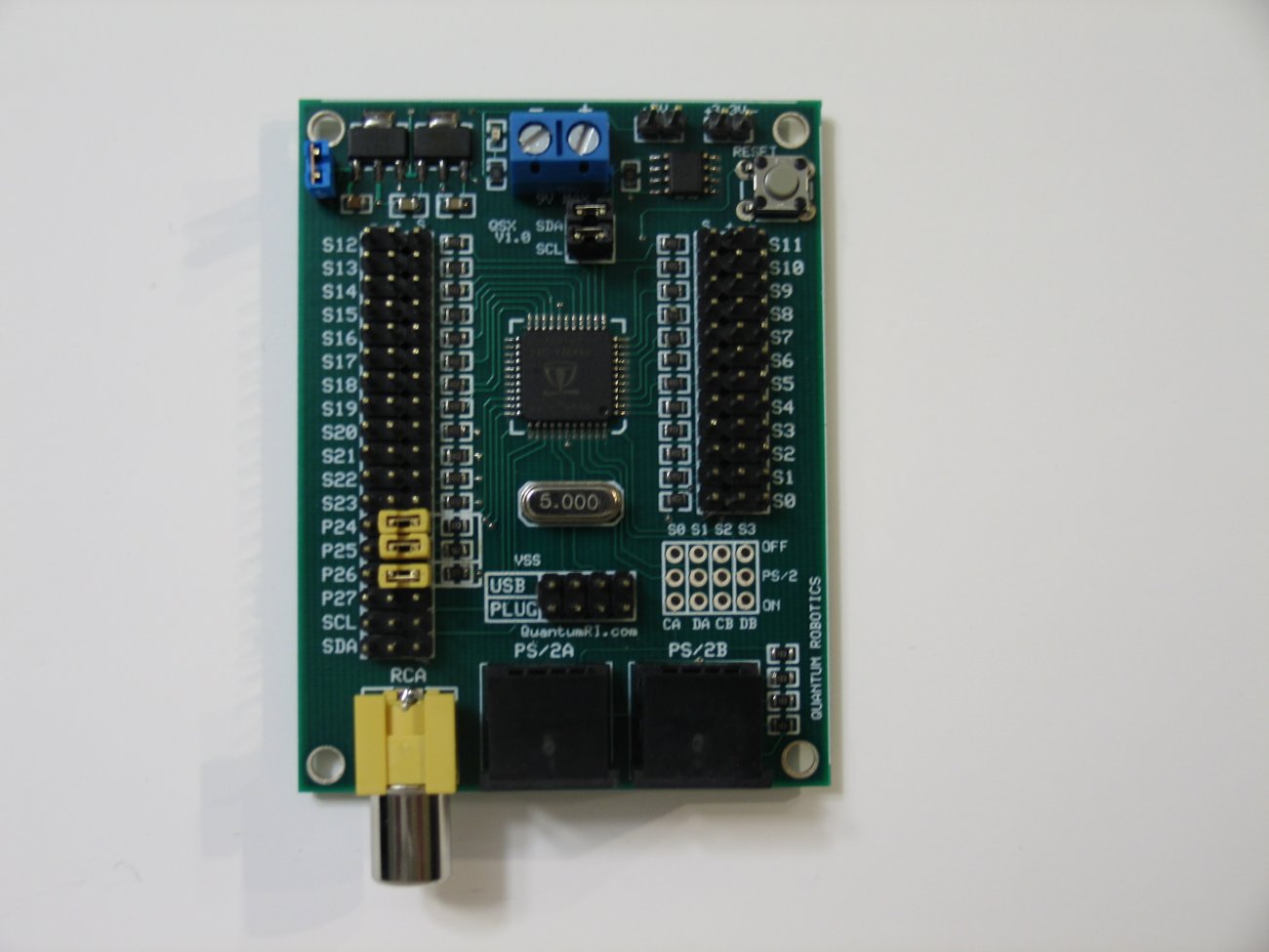
I did make a custom board(QSX-24 doc sheet attached) for this project and use them in all my robots.
I have a small limited amount left. I can solder some up, so if your interested they are $42.00 shipped.
Video:
http://www.youtube.com/watch?v=3a8VUFqnO0c
Below are some pics & code. The hexapod was used in the demo video.
Paul
I have ported over some code to the Propeller platform along with a lot of tweaking and with the help of several objects from the object library.
It's a software package that controls a hexapod. It can technically be modifed to run any X legged robot. Each leg has to have 3DOF.
And any size as long as you change the basic body and leg dimensions.
It's a Inverse Kinematic solution and it computes everything on the run. Currently all the math is done in spin.
I will be editing this with more details. But I have had several people interested in the code so here you go.
I did make a custom board(QSX-24 doc sheet attached) for this project and use them in all my robots.
I have a small limited amount left. I can solder some up, so if your interested they are $42.00 shipped.
Video:
http://www.youtube.com/watch?v=3a8VUFqnO0c
Below are some pics & code. The hexapod was used in the demo video.
Paul


Comments
It seems you are missing some decoupling caps at the Propeller? Nothing between VDD and VSS at the Propeller, or are they underneath?
Jim
Schill I thought about modifing the code to do 2dof. Its not that complicated. Basically I was thinking that the last dof would still exsit in the software but it just dosent move. You just dont use it. Give it a value that never changes. The code would be larger than needed but easily converted back if you do go to 3dof. Just an idea.
Jim the decoupling caps are below the regulators in the pic. I used 3 surface mount caps. The values are in the schematic and that's in the word doc(I'll change this to a PDF). I've been using these boards for some time and have had no issues or problems. I assume that the chip would reset(like a brownout condition) if there was an issue?
Paul
I watched the 4 videos on YouTube. I like the Micro hexapod. What are the approximate dimensions of it? Will the circuit board fit? Will you be offering kits? (especially of the body parts) And finally, could you provide some more info on the $3 servos that you liked so much? (I hope that's not too many questions.)
Thanks. Al
I'll start a thread on the other bot in the next few days.
Here's a few answers to your questions.
I used 9g HXT servos from HobbyKing.com they are 2.69 a piece. Comparable to Hitec HS-55. There a little louder but the trade off is that their a beefier servo.
The little guy has a board, a small 800mah lipo, a 5amp UBEC, and a audiable battery warning circuit(from hobyking as well). But I had to trim the servo leads and crimp on new connectors.
There just to long and take up to much space. It's alot more work to assemble but makes for a neater wiring job.
As for the dimensions it would completely fit on a 8in dinner plate.
Yes I plan to make a small run at the shop. I might have something within a month or so. I dont like the legs and need to redesign them for better movement. Nothing drastic.
Ill have some more info on this guy soon.
You've done all the legwork, you could have a nice side business selling kits to build those, clearly there is a lot of interest here.
Bravo, VERY well done!
They always seem to be either too long or too short. I'd like to see more servo manufacturers just put a jack in the body of the servo instead of attaching a cable (similar in configuration to the Dynamixels (if not in function)).
Thanks for the information. I'll keep watching this forum for your updates.
Al
I would like to tell you all that I got 2 boards from Paul today, VERY NICE products!!
Been playing around all day with it, and It's all working perfect.
Thank's paul for a nice product, very fast delivery and perfect service.
Regards,
Niklas
The project is not dead. But I have been messing around with different materials for the kit. I've upgraded my milling machine(huge difference) and there's a new learning curve to different materials. I'll be posting some updates soon.
I've been working on a touch sensor for the feet. Something that will detect force applied, taken off, and just standing force. I hope that makes sense.
Niklas thanks again.
Paul
Re: The touch sensor for feet.
Will this potentially allow the robot to walk over certain low altitude obstacles it encounters?
--Bill
ps Do you have pictures/videos of your shop/mill?
I'm in the work of swooping "Brain" in my home made Phonex from Basic Atom Pro to one of your Prob-boards.
When I looked at the code I could not make out how to connect the servo's to the board.
"From your code"
'
'[PIN NUMBERS] This is a little confusing. Assign the P(x) variable with the actual physical pin being used.
' *Example* Using P3 below. My right rear hip servo(Coxa) is attached to pin 11 on the propeller.
P3 = 11 'Rear Right leg Hip Horizontal RRCoxaPin
If I would like to connect the 'Rear Right leg Hip Horizontal' servo to the board, should i connect it to the pins marked with "S11" or to pins marked with "S3" ??
Or should i go for the physical pin on the MCU chip (Pin 11) ?
And also, In the code you start the PS2 with "FirstPin" 24, when connecting my PS2 to "P24" on the board I can't get it to work.
But when using "FirstPin" 0 and connecting the controller to "S0" on the board, it work's perfect.
(I took the Red jumpers off the P24, P25, P26 when trying to connect to PS2.)
And.... It would be very interesting to try the "*LEG CALIBRATION SOFTWARE*" that you mention in the code..
regards,
Niklas
I have changed this in the next version V4 of the code as well with some added functions/features. Poor choice in variable names at the time. But yes ignore the P3 in P3 = 11. Hook the Right Rear Coxa servo to S11 on the board. This applies to the reset of the servos as well.
ex: from the current code " P9 = 3 'Front Right leg Hip Horizontal RRCoxaPin " This servo would connect to S3 on the board.
Ill make a quick fix when I get home and will post on here.
For the PS2
The jumpers need to come off as these connect the rca when the jumpers are on. It should work off pin 24. They should be connected to the left most pins. Ill post a pic of this.
One more thing the voltage that is applied to the board is your servo voltage. That then goes thru the regulator to regulate down to 5v and to 3.3v for the prop. If you plan to use a lipo setup you need a ubec. Hobbyking has a few by turnigy that cost about 10 to 15 dollars. Not sure how you have your bot setup before the switch over.
@Bill
I basically have a simple push button detecting when the robot walking on something I have this working and will make a small video clip of this. It basically stops the legs motion as soon as it detects its stepped on something but at the same time keeping the body level/parallel with the floor. I'll make a video which will better demo this.
I'll pull this guy out tonight and work a little on him.
I have posted pics of the shop/mill before and I'll find the link to those.
Paul
Have you considered using the static dissipating foam that comes with chips? Its resistance changes when it is compressed. You might be able to gain more information than simply on or off. You could see how the weight of the bot is distributed among the legs.
Duane
http://www.trossenrobotics.com/store/p/6492--2-Inch-Force-Sensing-Resistor-FSR-.aspx
But I have to come up with a way to build it into the leg.
I saw your new Hexapod and it looks AWESOME! Maybe Parallax would sell your kits?
I have tryed everything regarding the ps2.
as long as i use pins lower then 21 it's working.
Pin 20 is the last working one on both my boards.
I used 3 different controllers when testing. All 3 gave the same result.
Is it easy to change the servos to other pins in the software?
Hope to see the new version and more info a.s.a.p
Regards
Niklas
About the ps2 controller what type of controller do you have? Manufacturer?
Since it works on the other pins I dont think this is a issue.
You can changing the poll rate try anything from 1000 to 10000
You change that in this line of code.
And the start pin is 24 in the sample below.
PUB Start
F.start
SERVO.Start
PS2.Start(24, 10000) 'first_pin 0, Poll every 10ms
I attached a pic of the pins used to connect the PS2 and circled them.
And you need pull those jumpers as well.
OK
I have been using the PS2 controllers for some time now and could not understand what was wrong..
Now I see it!
I connected the controller to the inner pins, opposite to the ones you highlighted in the image
I will try it tomorrow (it's late here in norway now
Thanks again
/Niklas
PS:
I added one of the boards to my Biped and WOW!! Propeller is so much fun compared to Basic Atom Pro.
That's great! You'll have to post a video and maybe write it up for the project page!
I have also included the leg configuration file. Its basically a easier way to figure how much to offset your servos for the V3.1 code.
This will be an interesting day, Getting the Hexapod up and running on Propeller "brain" with the new version of the code.
I will try to get a video of the Biped. I still have to do some tinkering with my code.
I dont have IK running for the gait, all the walking is made manually and hard coded.
Im looking for some code using IK for Biped, when I find it I will try to apply it for better moves.
The hexapod will have object tracking via bluetooth link to my Laptop running Roborealm.
If I get time, I will add a project thread for both.
/Niklas
The hexapod is setup and I have been trying to tune all the servos.
I did not get the "Fine Tune" part of the code. It should be 650 ? How do I calculate what to enter here from the values I get when centering the servos?
The Robot enters the start possession and all seems to be OK, but when I try to do anything after that, the robot moves the front leg's all the way to the left and gets stuck there.
After that I cant do anything.
I do believe that it's my power supply thats doing this. Because when this happens I loose connection to the controller.
I will hook up some measuring devices and have a look at it.
I have BIG 15kg torque servos and they like to have a lot of amps
Hope to get some more done tonight.
(This is fun, The inner child is awake again
Ohh..
I did a small program that let's you select a servo and use + and - to move the servo from the 1500 center value.
The values are stored in a table and afterwords you can print it out in the Serial Terminal.
I was hoping to understand the fine tune part of the code and then get my small program to print out a table thats ready to "Copy and paste" to the main program.
Regards,
Niklas
Would you be willing to share your design files for milling the legs and body of you robot?
Thank you!
-Tim
I think Paul K has had good success using $3-5 servos, but he would have to fill you in on the details...
Still hoping for an update on your code.
I assume your newest code includes communication with your cool controller.