

Joe Grand's Laser Range Finder: A Development Diary
 Joe Grand
Posts: 70
Joe Grand
Posts: 70
Hi all-
I originally mentioned that I was designing a low-cost Laser Range Finder (LRF) for Parallax back in their 2009 catalog. The project has been moving along sporadically in a vacuum since then and I thought it would be fun (and hopefully informative) to use this Forum thread as a way to keep folks updated with my progress and to solicit any comments along the way.
Theres a danger of publicly documenting an in-progress design, since lack of consistent updates will cause people to think the project has been abandoned. Not true in this case - Im working on this design in parallel with some other projects. Sometimes Ill have more time to focus and, hence, make strides quickly, and other times Ill be working on other things or waiting for parts/materials to arrive. Ill try and post when I have something useful to share or run into some development problem.
Initial attempts
Most of the past year has been spent researching and evaluating various range-finding methods and trying to settle on a design direction that is suitable for a low-cost/hobbyist environment.
My original plan way back at the beginning was to use the time-of-flight method (http://en.wikipedia.org/wiki/Time-of-flight and http://www.repairfaq.org/sam/laserlia.htm#liarfbl) to measure the travel time from laser light leaving the laser and being received by the detector. I built a high-speed time-to-digital converter using the ACAM GP2 (http://www.acam-usa.com/GP2.html) and a Parallax SX, and had a Data Delay Devices 3D3608 programmable pulse generator (http://www.datadelay.com/asp/oscpg.asp) generating pulses in a range of 14ns to 1.3uS that was to be used to trigger the laser driver circuitry.
Heres a short video I made for Ken Gracey/Parallax in mid-2009 just to demonstrate the subsystems: http://www.youtube.com/watch?v=BlQhr8Jtl_A
I had also considered phase-shift measurements, which compares the phase shift between the outgoing modulated laser and its reflected light.
The high speed circuitry required for both systems is non-trivial and too much in the analog domain for me (Im primarily a embedded/digital engineer), so I scrapped this approach. Both designs would also need specialized optics and the circuitry would be too finely tuned and precise for any user-based modifications/hacks.
Optical triangulation
I decided to go with the method of optical triangulation whereas the distance to a targeted object is calculated using triangulation with simple trigonometry between the centroid of laser light, camera, and object. The most compelling example is the Webcam Based DIY Laser Rangefinder (http://sites.google.com/site/todddanko/home/webcam_laser_ranger) and my design is based, in theory, on this implementation.
Optical triangulation for range finding has been discussed previously elsewhere on the Parallax forums, but nothings out there as far as a fully developed, compact, easy-to-use module:
My first foray using this technique was using a Position Sensitive Detector as described by Roger Johnson and Chris Lentz's 2-D Optical Position Sensor article (Circuit Cellar #152, March 2003). A PSD gives excellent resolution and accuracy (0.0001 and 0.001, respectively), but only for a limited detection range as the sensor is designed for sensing light shined directly onto its face, not capturing reflected light.
This approach ultimately turned into the Laser Position Sensor module (Parallax part #NFS001) that we recently released as open-source with no plans to manufacture due to cost of the PSD sensor (~$30 in volume) and expected low-volume sales.
My finalized design direction is to use a Propeller as the core, an Omnivision OVM7690 640x480 CMOS camera module (http://www.ovt.com/products/sensor.php?id=45), and a laser diode. The OVM7690 is a really nice, compact device with fixed focus, integrated lens. The LRF module will be open source to the extent possible. Omnivision requires an NDA in order to obtain data sheets and communication information, so we'll need to work with them further to figure out what we can publicly release.
I particularly like this approach, as the design combines a few separate subsystems that could ultimately end up being used as separate pieces - the CMOS camera system and laser driver system. I also hope that by using a Propeller, folks will take advantage of hacking/modifying the module for more vision/camera/imaging applications above and beyond the basic laser range finding functionality.
To me, simplicity for the user is key. Like previous modules Ive designed for Parallax (Emic Text-to-Speech, RFID Reader and Read/Write, GPS Receiver), the LRF will have a simple serial communications interface for sending and receiving commands. Most likely it will be a 4-pin device: VCC (5V), SIN, SOUT, and GND.
In May 2009, early in my experimentation with optical triangulation, I made a video for Ken/Parallax to demonstrate a prototype using a CMUcam2 and a Freescale QG8. It worked surprisingly well given the low CMUcam2 resolution (176x255) and I could get 1/4 inch accuracy and distance range from 7 inches to 40 inches: http://www.youtube.com/watch?v=-h5ctq7dE9k

I think range and accuracy will dramatically improve using 640x480 resolution and further experimentation will be necessary to determine the ideal width of the module (distance between the laser diode and the camera), which will be an engineering trade-off of size v. measurement range. Possibly the camera and laser diode subsystems could be on a single module, but scored to make it easy for hackers/customers who want a different configuration or larger width to do so by snapping the board in half and re-calibrating.
Work to date
Since the video of the CMUcam2 and Freescale QG8 was made, Ive successfully put together a version using the CMUcam2 and Propeller:

Ive ported the triangulation math from the QG8 to the Propeller, so I can calculate the range to an object given pixel count from the center of the laser dot to the center of the camera module (which the CMUcam2 returns from its color tracking function call). For what its worth, Ill be releasing the code and hastily-drawn schematic for this version once I make some more progress and have some time to go back and clean things up.
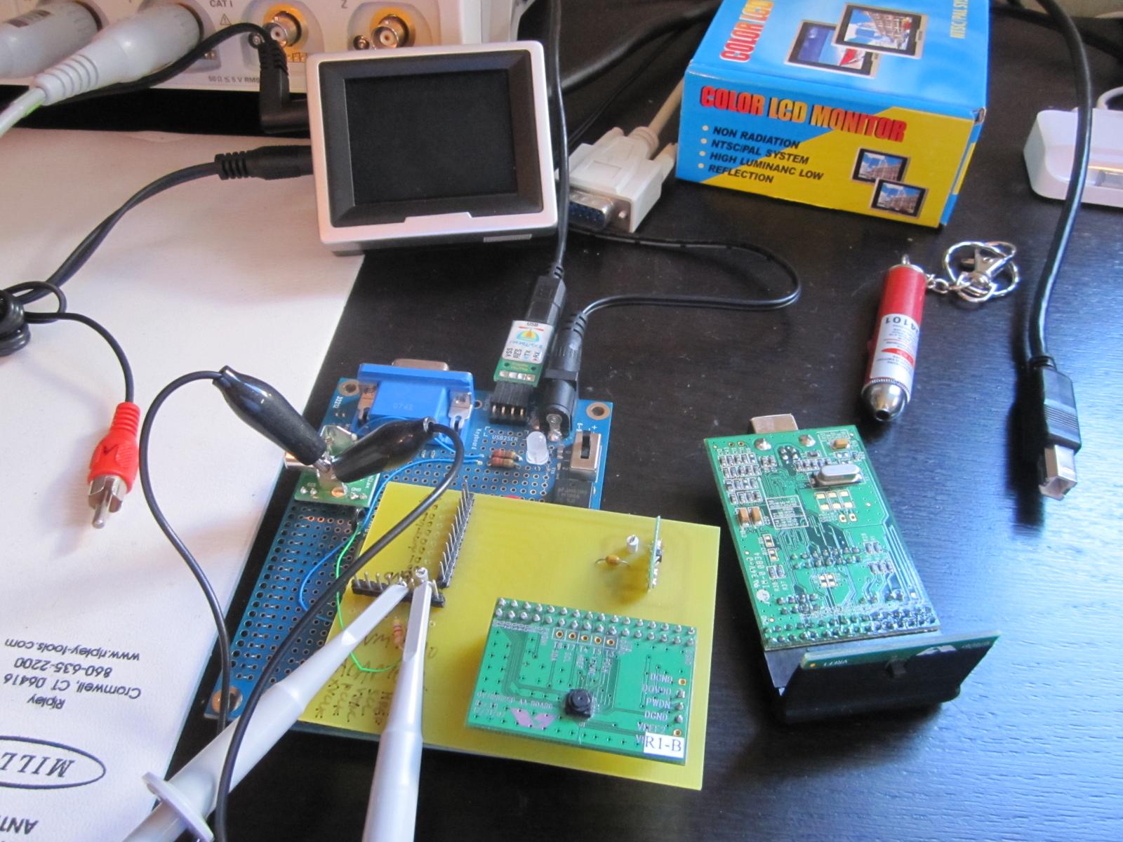
The prototypes using the CMUcam2 proved that Im on the right path with optical triangulation, but I needed to continue development using the actual OVM7690 camera. Instead of relying on the high-level image processing that the CMUcam2 provides, Ill need to create the color tracking routines directly on the Propeller. So, I built a hardware development platform using a Propeller Proto Board, OVM7690, and custom PCB holding the associated control/interface circuitry:
Last week, I finished up the camera communications interface, so I can now send commands to and configure the OVM7690.
Next steps
I feel like I've made some very good progress so far.
Up next is to finish the start-up/initialization routines for the camera, complete my evaluation of suitable laser diode/driver circuitry, and try to capture some data.
I also plan on diving into Hanno Sanders DanceBot vision tracking code (http://www.circuitcellar.com/archives/viewable/224-Sander/index.html and in Chapter 7 of the Programming and Customizing the Multicore Propeller Microcontroller book, Parallax part #32316).
Hannos ViewPort application (http://hannoware.com/viewport/) supports the OpenCV library for computer vision, which should give me a nice head-start on dealing with the actual color tracking of the laser dot (once I can successfully capture a video frame from the OVM7690).
Whew - that was a really long post! If youve read this far, let me know if you have any initial thoughts and if you enjoy the idea of my posting of development progress to the Forums!
Take care,
Joe
I originally mentioned that I was designing a low-cost Laser Range Finder (LRF) for Parallax back in their 2009 catalog. The project has been moving along sporadically in a vacuum since then and I thought it would be fun (and hopefully informative) to use this Forum thread as a way to keep folks updated with my progress and to solicit any comments along the way.
Theres a danger of publicly documenting an in-progress design, since lack of consistent updates will cause people to think the project has been abandoned. Not true in this case - Im working on this design in parallel with some other projects. Sometimes Ill have more time to focus and, hence, make strides quickly, and other times Ill be working on other things or waiting for parts/materials to arrive. Ill try and post when I have something useful to share or run into some development problem.
Initial attempts
Most of the past year has been spent researching and evaluating various range-finding methods and trying to settle on a design direction that is suitable for a low-cost/hobbyist environment.
My original plan way back at the beginning was to use the time-of-flight method (http://en.wikipedia.org/wiki/Time-of-flight and http://www.repairfaq.org/sam/laserlia.htm#liarfbl) to measure the travel time from laser light leaving the laser and being received by the detector. I built a high-speed time-to-digital converter using the ACAM GP2 (http://www.acam-usa.com/GP2.html) and a Parallax SX, and had a Data Delay Devices 3D3608 programmable pulse generator (http://www.datadelay.com/asp/oscpg.asp) generating pulses in a range of 14ns to 1.3uS that was to be used to trigger the laser driver circuitry.
Heres a short video I made for Ken Gracey/Parallax in mid-2009 just to demonstrate the subsystems: http://www.youtube.com/watch?v=BlQhr8Jtl_A
I had also considered phase-shift measurements, which compares the phase shift between the outgoing modulated laser and its reflected light.
The high speed circuitry required for both systems is non-trivial and too much in the analog domain for me (Im primarily a embedded/digital engineer), so I scrapped this approach. Both designs would also need specialized optics and the circuitry would be too finely tuned and precise for any user-based modifications/hacks.
Optical triangulation
I decided to go with the method of optical triangulation whereas the distance to a targeted object is calculated using triangulation with simple trigonometry between the centroid of laser light, camera, and object. The most compelling example is the Webcam Based DIY Laser Rangefinder (http://sites.google.com/site/todddanko/home/webcam_laser_ranger) and my design is based, in theory, on this implementation.
Optical triangulation for range finding has been discussed previously elsewhere on the Parallax forums, but nothings out there as far as a fully developed, compact, easy-to-use module:
- [post=813695]Phil Pilgrim using a TSL1401-DB linescan imaging sensor (June 2009)[/post]
- [thread=89395]Discussion of time-of-flight and explanation of triangulation (~November 2006)[/thread]
My first foray using this technique was using a Position Sensitive Detector as described by Roger Johnson and Chris Lentz's 2-D Optical Position Sensor article (Circuit Cellar #152, March 2003). A PSD gives excellent resolution and accuracy (0.0001 and 0.001, respectively), but only for a limited detection range as the sensor is designed for sensing light shined directly onto its face, not capturing reflected light.
This approach ultimately turned into the Laser Position Sensor module (Parallax part #NFS001) that we recently released as open-source with no plans to manufacture due to cost of the PSD sensor (~$30 in volume) and expected low-volume sales.
My finalized design direction is to use a Propeller as the core, an Omnivision OVM7690 640x480 CMOS camera module (http://www.ovt.com/products/sensor.php?id=45), and a laser diode. The OVM7690 is a really nice, compact device with fixed focus, integrated lens. The LRF module will be open source to the extent possible. Omnivision requires an NDA in order to obtain data sheets and communication information, so we'll need to work with them further to figure out what we can publicly release.
I particularly like this approach, as the design combines a few separate subsystems that could ultimately end up being used as separate pieces - the CMOS camera system and laser driver system. I also hope that by using a Propeller, folks will take advantage of hacking/modifying the module for more vision/camera/imaging applications above and beyond the basic laser range finding functionality.
To me, simplicity for the user is key. Like previous modules Ive designed for Parallax (Emic Text-to-Speech, RFID Reader and Read/Write, GPS Receiver), the LRF will have a simple serial communications interface for sending and receiving commands. Most likely it will be a 4-pin device: VCC (5V), SIN, SOUT, and GND.
In May 2009, early in my experimentation with optical triangulation, I made a video for Ken/Parallax to demonstrate a prototype using a CMUcam2 and a Freescale QG8. It worked surprisingly well given the low CMUcam2 resolution (176x255) and I could get 1/4 inch accuracy and distance range from 7 inches to 40 inches: http://www.youtube.com/watch?v=-h5ctq7dE9k
I think range and accuracy will dramatically improve using 640x480 resolution and further experimentation will be necessary to determine the ideal width of the module (distance between the laser diode and the camera), which will be an engineering trade-off of size v. measurement range. Possibly the camera and laser diode subsystems could be on a single module, but scored to make it easy for hackers/customers who want a different configuration or larger width to do so by snapping the board in half and re-calibrating.
Work to date
Since the video of the CMUcam2 and Freescale QG8 was made, Ive successfully put together a version using the CMUcam2 and Propeller:
Ive ported the triangulation math from the QG8 to the Propeller, so I can calculate the range to an object given pixel count from the center of the laser dot to the center of the camera module (which the CMUcam2 returns from its color tracking function call). For what its worth, Ill be releasing the code and hastily-drawn schematic for this version once I make some more progress and have some time to go back and clean things up.
The prototypes using the CMUcam2 proved that Im on the right path with optical triangulation, but I needed to continue development using the actual OVM7690 camera. Instead of relying on the high-level image processing that the CMUcam2 provides, Ill need to create the color tracking routines directly on the Propeller. So, I built a hardware development platform using a Propeller Proto Board, OVM7690, and custom PCB holding the associated control/interface circuitry:
Last week, I finished up the camera communications interface, so I can now send commands to and configure the OVM7690.
Next steps
I feel like I've made some very good progress so far.
Up next is to finish the start-up/initialization routines for the camera, complete my evaluation of suitable laser diode/driver circuitry, and try to capture some data.
I also plan on diving into Hanno Sanders DanceBot vision tracking code (http://www.circuitcellar.com/archives/viewable/224-Sander/index.html and in Chapter 7 of the Programming and Customizing the Multicore Propeller Microcontroller book, Parallax part #32316).
Hannos ViewPort application (http://hannoware.com/viewport/) supports the OpenCV library for computer vision, which should give me a nice head-start on dealing with the actual color tracking of the laser dot (once I can successfully capture a video frame from the OVM7690).
Whew - that was a really long post! If youve read this far, let me know if you have any initial thoughts and if you enjoy the idea of my posting of development progress to the Forums!
Take care,
Joe
1793 x 1200 - 108K
803 x 1200 - 68K

1600 x 1200 - 223K
Comments
It's great to see the post on the laser rangefinder. I think you'll find folks here love hearing about stuff like this, and for the most part understand the on/off, slow/fast cycles of development, and are usually pretty patient. If someone is really curious and there have been no updates for a while, you might see a Bugs Bunny post (What's up Doc?).
The explanation of what you've looked at, and what works/doesn't work and why was great! We look forward to hearing more from you.
John R.
Great! I'm looking forward to sharing more as I make progress!
Joe
Though time consuming and somewhat tedious, it wasnt particularly difficult. I ported the recommended start-up settings from a file provided with Omnivisions PC-based evaluation tool (that communicates to an Omnivision camera module over a USB interface) and reverse engineered a few additional settings (for example, reduced frame rate and disabling automatic white balance, which will come in handy for my initial attempts at capturing data and red laser spot detection, respectively) by watching the bus between the camera and host while selecting specific settings from within the PC tool. I then commented as many of the register settings as possible within my code to let me easily scroll through and identify what values do what.
All told, there were ninety-eight (98!) 8-bit registers that needed to be configured to get the OVM7690 module up and running, including, but not limited to, general settings, output format selection, resolution, video output speed/frames per second, lens correction values, color matrix values, edge and de-noise settings, Automatic Error Control (AEC), Automatic Gain Control (AGC), Automatic White Balance (AWB), gamma values, and flicker control.
I can monitor the digital video lines (8 bits), HREF (Horizontal reference), VSYNC (Vertical sync), and PCLK (Pixel clock) outputs from the OVM7690 on my scope, so the next step is to capture a video frame with the Propeller!
Joe
Well, this is way cool! I will watch you progress.
--Bill
I use some industrial sensors based on the triangulation technique. Ideally I would like them to be faster (they quote 2ms to 10ms), and to better understand the small error that occurs as the beam lands on different colours
It's very likely that my system will be slower, as the CMOS camera frame rate is 30fps (at maximum) and I'll need to do some basic vision processing once the image (or portion thereof) is in hand. So, it will probably be ~30Hz/33ms per measurement. This may preclude use of the module for high-speed applications - I think the sensor will find the most usefulness in indoor robotics navigation/object detection, but also hope the module will be used/hacked/modified for other scenarios that I haven't thought of.
As for small errors with different colors/objects, that will be interesting to experiment once the basic system is completed. Since I'll be looking for the brightest/most saturated red spot within a portion of the frame (some distance above and below the horizontal center), even against different colors, a red laser should still appear more red than other things in the field-of-view. I think I'll run into some limitations, however, like being in an outdoor environment, bright ambient light/sunshine, or if there's a reflection from another light source on an object that my system accidentally thinks is the laser spot. There are tricks we can do to help limit erroneous data, but the challenge will be doing so with the memory constraints within the Propeller.
Joe
Also, if you scan twice -- once with the laser on, and once with it off -- you'll be able to subtract the ambient light for an even more accurate reading.
-Phil
Agreed. That will help to give me the true centroid of the laser spot.
Good idea, but not sure if I'll have the memory to do so? I'm thinking of reducing the camera resolution to 320x240 (which will give me an increased 60fps as a bonus) and, if I limit the "window" of the video frame to the section I'm only interested in (some amount of pixels above and below the horizontal center), that might work. I'm trying to fit the frame buffer into the Propeller's main RAM (32KB) while still retaining a full 8-bits per pixel. I'm working on the calculations now to see what I can pull off. Maybe I could calculate things on-the-fly instead of storing into a large buffer, but having support for a buffer will be helpful to people who want to use the module for non-range-finding functionality and take more advantage of the camera's capabilities.
Joe
Since you're only interested in the X-position of the spot, you might be able to get by with summing intensities along the Y-axis, either over the entire image, or in broad, overlapping horizontal stripes. This will necessitate the ambient subtraction, though, since a cluster of semi-bright ambient pixels will sum to as much as one bright laser pixel.
Another tactic would be, for each X-position, just keep track of the value of the brightest red pixel, or n brightest red pixels, over all the Y's.
-Phil
Was curious as to the make and model of your scope in the background?
That is the love of my life - an Agilent DSO7054A 500MHz DSO.
Joe
You could do the two pass difference "in place" so that it only requires one frame sized buffer.
Great idea
I'm struggling with frame buffer size v. available RAM right now and am writing up a piece for my next "diary" post. With 640 pixels across @ 16-bits per pixel (YUV422 format. which I'm assuming is better than RGB format for the laser detection over a wider variety of lighting conditions) and assuming I want to use hub RAM (maximum 32K, but really only about 24KB available right now), that means:
640 * 16 = 10240 bits/line = 320 words/line
24KB = 6144 words
6144 words / 320 = 19.2 lines
So, I'd basically have a thin band around the X axis, +/- 10 lines. This might be OK for the red spot/blob detection, since I'm only really concerned with the X axis since that's where my camera and laser diode are located. Any red spot far away from Y = 0 probably isn't the laser, anyway.
Joe
Are you getting images from your ov7690 yet? I noticed from your photo that you may have been having problems with IR light leaking into the back of the sensor and tried to mask it off the pcb with tape or something? We had a problem like that. Anyway, we built a project with the 7690 recently and haven't gotten very good images-- the edges seem out of focus, and there is a lot of blooming around any sort of light source.
Hopefully it is just settings, because as you said, there are many of them.
regards,
chris
I'm still working on getting images with the OVM7690 and Propeller, but I've been using the camera evaluation board and Omnivision's OVTATool for quite some time. The images look good enough to me - I'm not a video/image processing person by any means, but the image will certainly serve my purpose.
The electrical tape wrapped around the module was to block all light (not just IR) from entering the back of the sensor. Typically, these modules are meant to exist in a closed (e.g., dark) housing where light will only enter from the front. However, since I'm operating the module in a free (not closed) environment, light is entering from behind and illuminating some of the BGA pads and traces. I can see them on my sample pictures taken with the OVTATool and the electrical tape significantly reduces the problem, though I certainly won't be wrapping any production design in electrical tape!
Omnivision suggested that a PCB with black soldermask might also help. To me, this is a minor problem, as even having such "interference" on the image won't prevent me from proper red spot detection and range calculations. I'll have more details once I move away from Omnivision's evaluation and onto my first revision of prototype circuitry.
Take care,
Joe
I usually put a copper pour behind image sensor chips to completely block light from the backside. It can be a bit inconvenient, though, if it messes with the signal routing.
-Phil
Joe
I thought it would be good to post an interim update to keep the momentum going. Writing a diary like this is very useful as it serves as my reference notes and is easier for me to wrap my head around this whole project as I break the development into manageable chunks. Im learning a lot as I go and I hope you do, too, as you follow along.
With the Propeller-to-OVM7690 CMOS camera interface completed and all start-up routines/register settings properly configured in October, my current goal is to capture and display a single video frame from the camera.
Camera interface and color space
The digital interface from the OVM7690 is straightforward:
- DVP[7:0] (Digital video port): 8-bit wide output bus corresponding to pixel information sent in the selected output format from the OVM7690 (RAW RGB, RGB565, CCIR656, or YUV422/YCbCr422).
- VSYNC (Vertical sync): Indicates the beginning of a new frame by pulsing high.
- HREF (Horizontal reference): Indicates the start of the next row of pixels by pulsing high. By keeping count of the number of HREF pulses received since the last VSYNC, we can determine which horizontal line of the video frame we are currently on. This will come in handy for our purposes to ignore most of the video frame above and below a defined horizontal window, since the laser diode is on the same X axis as the camera and most of the frame will be unimportant.
- PCLK (Pixel clock): Asserted when valid pixel data is available on the DVP bus. For a 640 pixel line in YUV422 format (16 bits/pixel), we should see 10,240 pixel clock cycles after an HREF pulse.
The camera can support a maximum VGA 640x480 resolution and I have configured it for data output in the YUV422 format (http://en.wikipedia.org/wiki/YUV, more accurately YCbCr, http://en.wikipedia.org/wiki/YCbCr, which is used for digital, not analog, encoding of the information - the two are often used interchangeably which can get confusing). Y stands for the luma component - that is, brightness in grayscale - and Cb and Cr are chroma components - color differences of blue and red, respectively, but more easily understood as a two-dimensional coordinate space of color. The YUV format will be the most effective color space offered by the camera in helping me identify the red laser spot within the frame, as I can search for something with a high brightness (Y value) in the upper left corner of the graph (strong/positive Cr and weak/negative Cb).See http://upload.wikimedia.org/wikipedia/commons/d/d9/Barns_grand_tetons_YCbCr_separation.jpg for a color image and its separated Y, Cb, and Cr elements. See http://upload.wikimedia.org/wikipedia/commons/3/34/YCbCr-CbCr_Scaled_Y50.png for an example YCbCr plane with Y = 0.5.
YUV data can be stored in two distinct manners (http://www.fourcc.org/yuv.php):
- Packed, where Y, U (Cb) and V (Cr) samples are packed together into macropixels which are stored in a single array.
- Planar, where each component is stored as a separate array.
The OVM7690 uses a packed YUV422 format known as YUY2, in which each 16-bit pixel is given an 8-bit Y component and alternating 8-bit U or 8-bit V component as shown at http://www.fourcc.org/yuv.php#YUY2Y0U0 corresponds to a single pixel starting from the left, Y1V0 is the 2nd pixel, etc. Every location has Y data, and U and V are every other pixel. This will leave me with 640 Y pixels, 320 U pixels, and 320 V pixels for each line of a 640x480 frame. I believe this chroma downsampling is done as details in Y (brightness) are much more noticeable to the human eye than Cb or Cr, but Ill learn more about this as it comes time for actual image processing.
Memory constraints
The Propeller provides 32KB of RAM on its hub that is shared will all eight cogs. A portion of that RAM is allocated for the stack and operational variables and Id like to use the remainder to keep as large a video frame as possible. In the current iteration of my code, approximately 20KB (5,280 longs) is free for use.
To store a single video frame at the maximum 640x480 resolution at 16-bits per pixel, Id need 600KB of RAM, clearly way more than is available:
- 640 * 480 = 307,200 pixels
- 307,200 pixels * 16-bits/pixel = 614,400 bytes = 600KB = 153,600 longs
I investigated a few external memory options, but was concerned with the complexity (which goes against my design goal of having a simple, easy-to-hack platform) and speed bottlenecks that would be introduced by having the memory connected to the Propeller via I/O instead of being directly on the Propellers hub:- Averlogic AL422B FIFO frame buffer (http://www.averlogic.com/AL422B.htm) - Useful as a temporary storage buffer for the frame sent from the OVM7690 and can be retrieved by the Propeller at will. However, the Prop is fast enough to receive the frame directly and Id still need some memory area on the Prop to store the frame for image processing purposes. Costly at ~$7 in quantity.
- XGameStation Hydra Xtreme 512KB SRAM (http://www.xgamestation.com/view_product.php?id=43) - Andre provides a nice API (Spin and asm) for communicating with the SRAM. The web page says that the SRAM can be accessed as fast as hub RAM in many cases from within a COG, so there might not be a speed bottleneck here. It uses an ispMACH 4064 CPLD (in a 100-pin QFP) in between the Propeller and SRAM that acts as the memory controller and requires 12 I/O lines from the Propeller. However, even 512KB isnt quite enough for a full frame buffer at 640x480, 16-bits per pixel (wed need 600KB). The module itself is $59, but a similar solution could be designed directly onto the LRF board (see next bullet)
- 512KB (or greater) Parallel SRAM (e.g., Alliance AS6C4008) - Requires a significant number of I/O pins (address, data, control lines) and would eat up nearly all available pins on the Prop without having some external latches/logic (most of my pins are already taken for camera interface, status indicators, and serial interface for user control). Price for memory is currently around $4 in quantity for 512KB (4Mb) or $6-$7 for 1024KB (8Mb), though varies widely with manufacturer and distributor. Its also hard to negotiate pricing or secure an order, as most SRAM vendors are interested in 100K+ units a month.
- 32KB external serial SRAM (N256S0830 or 23K256) - Supporting speeds up to 10 or 20MHz and easy to integrate to a Propeller via SPI (objects are available from http://obex.parallax.com), the memory size is still too small for a full frame, but may come in handy later for reduced resolution and to free up the Propellers hub RAM for other functions, assuming the speed isnt a bottleneck.
Without having easy, low-cost access to a significant quantity of external RAM, Ill need a different approach and, for now, have decided to reduce the camera resolution to fit into a frame buffer within my Propellers available internal RAM.Later on, when it comes time for actual laser spot detection (and not just capturing and displaying a frame, which Im trying to do now), I plan to increase horizontal resolution to the maximum 640 across and limit my vertical resolution to something small to still allow me to fit within the Propellers hub RAM. This should be OK, since I'm only really concerned with the X axis as that's where my camera and laser diode are located. Any red spot far away from Y = 0 probably isn't the laser, anyway. I may try to process the incoming video on-the-fly instead of relying on a frame buffer as suggested by PhiPi, and use a smaller buffer to aid in the image processing/spot detection, though thats outside of my area of expertise right now.
Taking small steps
My current goal is to unpack the YUV422 data from the OVM7690 and make sure I can properly display an image. By setting the cameras resolution to QCIF (176x144) and processing only the 8-bit Y/luma component (ignoring the U and V values), I come close to fitting in my available RAM of 20KB (5,280 longs).
At QCIF resolution, I only need to allocate 24.75KB for the frame:
- 176 * 144 pixels * 8 bits/pixel of luma = 25,344 bytes = 6,336 longs
In order to fit into my buffer, Ill need to ignore the bottom 24 lines of the frame:- 5,280 longs = 168,960 bits
- 168,960 bits / 8 bits/pixel / 176 pixels/line = 120 lines
So, my image will be grayscale with 256 shades of gray at an effective resolution of 176x120. Im OK with this for now.I spent quite a bit of time reading various forum posts on TV and VGA output, hoping that I could take the digital signals from the OVM7690 and process them for use with a modified version of an existing TV/VGA driver:
- [thread=123324]Tv out with more colors and more pixels (June 2010)[/thread]
- [thread=120805]Modify TV object? (March 2010)[/thread]
- [thread=119588]Are there grayscale display driver for the Propeller? (January 2010)[/thread]
- [thread=123832]Better composite graphics available than the Prop? (July 2010)[/thread]
It seems that Id possibly be able to get an 8-bit grayscale output using a modified TV driver or display a reduced resolution, RGB color image using Kyes 160 x 120 6-Bits-Per-Pixel VGA Driver (http://obex.parallax.com/objects/686/). But, then I remembered that I dont need the Propeller to output video and Id only be using said video/image to ensure that the camera is working properly and for debugging while I moved forward with the project.I was hoping Hannos ViewPort application (http://hannoware.com/viewport/) would work for me, as its a very handy tool with nice video capture, filtering, and processing routines, among other things. But, ViewPort can only display video within its video widget if the video capture is in one of the modes defined in PropCVCapture.spin, which are all low-resolution, low-bit-per-pixel requiring a composite (analog) video signal going through an A/D as shown in his DanceBot vision tracking code (http://www.circuitcellar.com/archives/viewable/224-Sander/index.html and in Chapter 7 of the Programming and Customizing the Multicore Propeller Microcontroller book, Parallax part #32316). Maybe with some hacking or help from Hanno I could get something going this way, but Ive decided on a different approach that doesnt require Prop resources.
So, Im now working on a PC-hosted monitor program to try and offload the image display/processing, which is similar to other embedded camera systems like the CMUcam (http://www.cmucam.org), AVRcam (http://www.jrobot.net/Projects/AVRcam.html), and Parallaxs TSL1401 Linescan Imaging Sensor designed by Phil Pilgrim (http://www.parallax.com/StoreSearchResults/tabid/768/txtSearch/28317/List/0/SortField/4/ProductID/566/Default.aspx).
This will give me a nice interface to download the frame buffer from the Propeller and display a grayscale image. This same program will be enhanced later (once I get it working) to provide a GUI control interface for the LRF to configure the device, send commands, etc., which should be something very helpful for users of the final LRF product.
That's it for now!
Joe
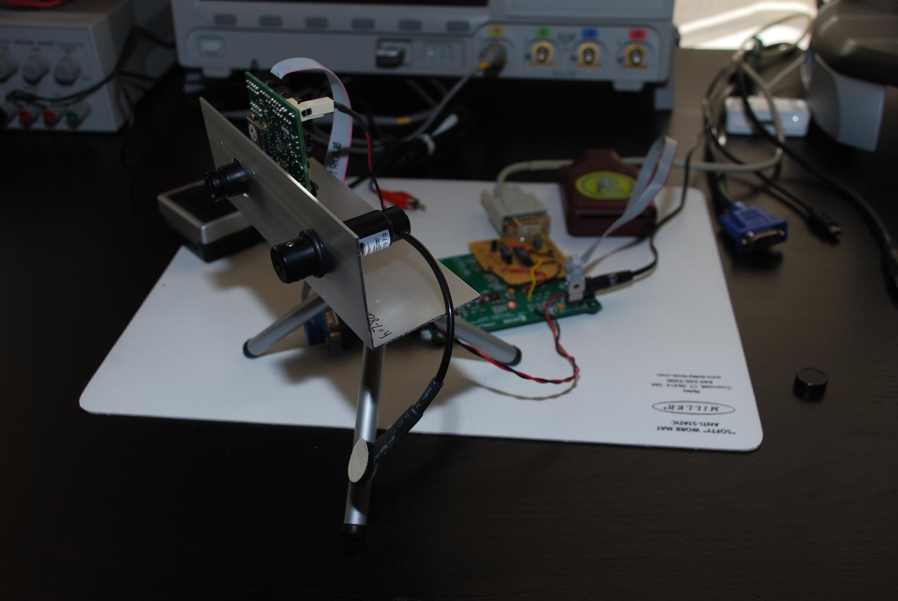
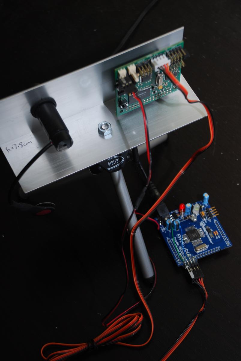
Tangential to working on the Propeller-to-OVM7690 CMOS camera software interface, Ive been spending time researching and evaluating various laser diode/driver solutions to provide the red laser spot necessary for my Laser Range Finder implementation (which, as described in [post=947589]my first post[/post], will use optical triangulation to determine distance by simple trigonometry between the centroid of laser light, camera, and object).
In researching ways of driving laser diodes, Ive identified three options, each with its advantages and disadvantages:
Initial thoughts
My first reaction was to go with an integrated driver solution from iC-Haus, since having a modular solution of separate driver and laser diode would allow the end user to replace the red laser diode that I ultimately selected with something more powerful or with a different wavelength. Then I thought about it some more and decided that very few people, if any at all, would actually want to modify the laser portion of LRF module, which is designed for such a specific purpose and instrumental in the proper operation of the Laser Range Finder.
Once I stumbled upon Arimas APC Laser Diodes, I was leaning heavily towards using them before I even received the samples. During my evaluation, Id be keeping my eye on three important criteria:
Evaluation results
I received a few different versions of the APC Laser Diode, ranging from the lowest-priced 650nm laser diode with plastic collimating lens (designed specifically for low-cost laser pointing applications) to a higher-end, 635nm version in a metal housing with glass collimating lens. All were Class IIIa devices with a maximum power output of >= 3mW.
While the plastic lens version is the smallest and lowest cost, it looks and feels bit cheap. But, in a way, its supposed to be! There were wide side lobes around the center spot visible at a distance of less than 24 inches, which may cause a problem during the LRF spot detection. The entire plastic housing glows when the laser is on, which might be nice for certain projects, but I found it to be distracting. Also, since Ill already have a multi-color status indicator light on the LRF module, I dont want to have such a noticeable red light on it. Some nice close-up pictures of the plastic lensed APCD-650-06-Cx device can be found here.
I then tried a 650nm version in a metal housing with glass collimating lens. The unit not only felt better (heavier, more robust), but had slightly better operating characteristics. Though side lobes were also visible with this version (apparently side lobes are due to having a too largely-sized aperture), they were much thinner and farther away from the center spot (e.g., far enough above/below the centroid to not be seen in the narrow detection window I plan to use in my LRF), and only visible at a distance of less than 7 inches. Another advantage of this version is the fact that the entire housing does not glow when the laser is enabled.
One aberration I did notice with the metal/glass version was a phantom image (which essentially looks like a very faint image/reflection) below the center laser spot. This is mainly a quality issue within the collimating lens or housing. I noticed this issue, which was visible to a distance of 36 inches, in both of the samples I evaluated. The phantom image was not noticeable at any distance when viewing the laser spot with the OVM7690 camera, and thats what matters most. While having increased quality of the laser spot would be nice (and Ive since notified Arima of my results and have requested such), its not absolutely necessary for this non-laboratory/non-scientific application, since all I need to do in practice is identify the laser spot within the frame and locate the center point.
As I was taking some screenshots of the laser diodes using Omnivisions OVTATool evaluation program, I noticed a significant difference in laser spot visibility using the 650nm laser diode versus the 635nm laser diode.
It turns out that the Omnivision OVM7690, like most webcam modules, has an IR elimination/cutoff filter (more recognizable to engineers as a low-pass filter) which will block infrared light and pass visible light. The typical cut-off for an IR filter is within the red wavelength, so a significant portion of the red light energy can be lost due to these filters. With the filter used on the OVM7690, 50% of the optical energy is lost at 650nm, which is exactly the wavelength of most red laser pointers! The david-laserscanner.com forum thread Impairment by IR filters - A further reason to prefer green has some additional details and good discussion of webcams IR filters. More optical power passing through the cameras filter means better detection of the red laser spot by the OVM7690 within an environment and, thus, a more likely successful laser range measurement.
The cost of the 635nm APC Laser Diode is essentially double ($7.55/1K) the cost of the 650nm ($3.65/1K). I think the increase is a worthwhile investment if it will make detection of the laser spot easier across a wider variety of objects, lighting conditions, and environments.
To try and qualify the effectiveness of the APC protection mechanisms and the reliability of the laser driver, I did some very simple tests of operating the device in over-voltage conditions (up to 5V where the recommended absolute maximum was 3.3V) and varying the input voltage level (quickly changing to simulate a noisy/unregulated supply). The Arima modules seemed to handle my abuse well. The output brightness of the laser spot appeared consistent in all cases.
Whats next?
All in all, Im pleased with the functionality and simplicity of the APC Laser Diode. There are enough other complex parts of this Laser Range Finder design to have to worry about properly driving and protecting a laser diode, yet alone sourcing even more components. Barring any unforeseen issues, Ill be using Arimas APCD-635-02-C3-A device.
With the evaluation and selection of a laser vendor complete, Im going back to focusing my efforts on finishing the Propeller-to-OVM7690 CMOS camera software interface to properly receive and display an image.
Wish me luck!
Joe
I just discovered your fascinating thread yeasterday! I spent a lot of years in the video industry and did some flying along the way so both interests converge in my brain as I read your posts. Airborne DME uses a pair of pulses that are subsequently delayed by the ground station before being returned as a form of identification of the response for the inquiring aircraft. If you were to send the laser signal out as a pair of say 3 pixel wide pulses with a 3 pixel delay and only sent for 10 lines say 250 Hlines from the end of vertical blanking, would that provide you with easier processing of the signal? Any light pattern that did not conform to the on off on pattern could be ignored and the video display software turned to video processing software could easily handle the syncing of the laser from the end of V to the end of H for the start of the laser pulse. You also could probably ignore the Cb signal as you have already discovered, the red light content in that signal is non existant or very little. You could experiment with the pixel clock to determine when to start the laser pulse after Hsync to maximize Red content of the received signal.
Just a few crazy thoughts. Keep up the great work and keep us posted on your fascinating project.
RS_Jim
Thanks for reading!
Interesting idea. I'm not sure the response time of the laser driver is fast enough to turn on and off directly from the video signal. Even at a pixel clock of 2MHz, a 3 pixel wide pulse would be very fast at 1.5uS. In the method I'm using, I can simply turn on the laser diode, take a frame capture, turn off the laser diode, take another frame capture, and subtract the two frames to easily identify where the laser spot is within the frame. It's still TBD, but I may not even need to do that since I should be able to just look at a single frame for the brightest red spot.
Just yesterday I received my first frame from the camera, so I'm making some good progress that I'll update on a little later when I have more to show.
Joe
Ok, I never thought about the response time of the laser diode. I did have another thought about the memory issue. The old collins DME that I once read the book on, used a scanning tecnique that allowed it to lockon to return signals not knowing initially how far away the ground station was. I thought that might apply to this project. If you create a blanking window that is say 20 lines high and 64 pixels wide you would only need 640 longs of hub ram to store the video for processing. It would be like cutting a hole in a black piece of paper, holding it away from your eye and moving it from side to side until you see the spot. 64 pixels wide means that in 10 frames you could have examined the whole width of the image. Running the first scan without the laser would give you a series of peak values that you could subtract from the next scan with the laser turned on. Once the pixel position is determined, the window can be centered on the laser return and its position maintained by some PID software. My guess is that with so many H lines being ignored during the verticle scan, you would have lots of time for processing.
Keep us informed as to your progress, I would love the have the time and budget to play with that and some other projects like it. I have been noodling for a long time as to how to build a VOR for robots that would allow location when GPS signals were not available. Like inside a building.
I am enjoying your progress updates on this as much as I enjoyed "Prototype This".
RS_Jim
That's another interesting thought. However, the maximum pixel clock I can achieve due to the speed limitations of the Propeller (even when overclocked) is 2MHz, which, depending on resolution, could account for a very slow frame rate. So, if I needed to take a large quantity of frames (e.g., 10) just to perform a single range calculation, I think the system would end up being too slow to be useful.
I should actually be OK with available main/hub RAM in the Propeller, since I'm limiting my visible window (aka Region of Interest) to 640 pixels wide by some small number of pixels high (maybe 40, which would give me 20 pixels +/- the horizontal center line). For my application, I'm not concerned with anything outside of that area.
Take care,
Joe
I've finally completed the frame grabber firmware to successfully retrieve images from the Omnivision OVM7690 via the Propeller!
For testing, I currently have the OVM7690 set up for QCIF (176 x 144) @ 2MHz PCLK and my system is grabbing a 176 x 120 frame (ignoring the last 24 lines due to memory constraints mentioned in [post=959702]an earlier post[/post]) and only looking at the Y byte of each pixel (thus, giving me a greyscale image). I dump the frame to the Parallax Serial Terminal, copy the bytes into a hex editor, save it as a .RAW, and import into Photoshop.
A detailed write-up will come shortly with more pictures and video!
Joe
That's a nice quality image! (8-bit pixels?) How long does it take to capture one frame?
-Phil
Yes, 8-bit pixels. The camera actually outputs YUV422 with 16-bit pixels (8-bit Y, 8-bit U/V), but I'm ignoring the chroma information for now (I'll obviously need to look at that for laser spot/color detection, just haven't gotten there yet). I haven't taken exact measurements, but at the 2MHz pixel clock (PCLK), it should be around 175mS to capture an entire frame, including some post-processing. I basically have 24 cycles to grab each pixel and 24 cycles to do something with it before the next pixel comes along. I'll be able to shave some cycles in my next revision of hardware by moving the data lines to P7-P0 to avoid having to shift.
I (or other Propeller heads) may be able to do/suggest some additional optimizations once the whole system is up and running, but I'm certainly pleased so far!
Joe
As briefly mentioned in my [post=974904]previous post[/post], I've finally completed the frame grabber firmware to successfully retrieve images from the Omnivision OVM7690 via the Propeller. Saying this was a tricky part of the project would be an understatement, but the results thus far are worth the effort.
My first attempt at retrieving the digital video signal from the OVM7690 worked fine in theory, but the routine was written in Spin and too slow for the camera even at a severely reduced pixel clock (PCLK) well below the 2MHz I ultimately ended up using. The function waited for VSYNC to go high (which signaled the start of a new frame), then waited for HREF to go high (which signaled the start of a new line), and then monitored PCLK to receive each Y/luma data byte (the first 8-bits of each 16-bit pixel) from the camera and store it into my frame buffer. Due to the overhead of Spin, I was missing many of the pixels and it was evident that Id need to port the frame grabber to PASM for speed and efficiency.
Timing is everything
I was apprehensive to create a new cog and write in PASM, but while browsing Chapter 3 (Debugging Code for Multiple Cores) of the Programming and Customizing the Multicore Propeller Microcontroller book (Parallax #32316), I stumbled across the Propeller Assembly Sourcecode Debugger (PASD) (http://propeller.wikispaces.com/PASD and http://www.insonix.ch/propeller/prop_pasd.html). Using the PASD example on page 111 of the book combined with PASD_AsmDebugDemo.spin included with PASD, I was able to control a blinking LED from my PASM cog in about an hour. Having debugging capabilities (in particular, single stepping and viewing hub and cog RAM) is a huge time saver. With that said, writing my full frame grabbing cog still took a solid, full time week of work.
Instead of having the cog run all of the time, repeatedly grabbing a frame and putting it in the frame buffer (stored in hub RAM), I decided to have the cog only run when started by a calling object, grab a singe frame from the camera, and store it in the frame buffer. This prevents possible erroneous results if my image processing routine (running in my top object) is examining hub RAM while new values from the next frame are being written into it by the frame grabber cog. After the frame is stored in the frame buffer, the cog then sets a flag in hub RAM to a non-zero state so the calling object knows that the frame grab is complete. The cog then stops itself.
I had to overclock the Propeller to 96MHz (using a 6.0MHz crystal) in order to meet the timing requirements of the camera and properly read and process each pixel in time before the camera is ready with the next one. Even at a relatively slow PCLK of 2MHz (compared to 24MHz or greater that we see on high-end microprocessors with dedicated video processing hardware), I only have 0.500uS to properly grab and store each pixel. At 96MHz, where each cycle takes 0.01042uS, that equates to 48 cycles. Since most instructions on the Propeller take 4 cycles, I dont have much to work with!
Because the cameras image data (passed in on D7..D0) is only valid when PCLK is high, I had to make sure I read the data within 24 cycles, the first half of PCLK. Then, I have the next 24 cycles, while PCLK is low, to store the data into the frame buffer and increment counters/pointers.
Increasing the Propeller clock to 100MHz would have given me a few extra cycles, but the 6.25MHz crystal (offered by Parallax #251-06250 and Mikronauts) required for the overlock is not a common, off-the-shelf value and Id be limited to a single source. Though most crystal manufacturers will create a custom frequency part with a minimum order quantity of 1K, I like the option of using readily-available components that have multiple vendors whenever possible.
I see me!
For testing, I currently have the OVM7690 set up for QCIF (176 x 144). My system is grabbing a 176 x 120 frame (ignoring the last 24 lines due to memory constraints mentioned in an earlier post) and only looking at the Y byte of each pixel (which will give me a greyscale image). It takes about 175mS to capture an entire frame, including some necessary post-processing of the data. To create a bitmap image for viewing, the frame is dumped to the Parallax Serial Terminal. I then copy the bytes into a hex editor, save it as a .RAW file, import the .RAW into Photoshop, and save it as a .BMP. A friend of mine commented that I should have used a scripting language like Python to automate this process, but this manual method worked just fine for development purposes.
Heres a video of the process in action:
http://www.youtube.com/watch?v=URqUYhg4IvI
The OVM7690 has a nice feature of providing color bars for testing. The color bars are enabled by setting a single bit in one of the cameras registers and they are overlaid onto the camera image. To guarantee that all I would see were the color bars, I put a piece of black electrical tape over the cameras lens. I used the PC-based OVTATool2009 (that communicates to an Omnivision camera module over a USB interface) with my OVM7690 evaluation board to obtain an image of what the color bars would look like in greyscale, so Id have a reference to compare the image created by my system with.
Surprisingly, on my first attempt of dumping a frame, a somewhat recognizable image of vertical bars appeared, but they werent the color bars I was hoping for. It took me a few days of to tweak some of the frame grabber cogs timing (as I was accidentally missing pixels, causing the image to look corrupted) and to fix some incorrect automatic exposure settings (which were giving me extremely dark images). Once I got things properly working, the color bars appeared as an exact match to my OVTATool2009 reference image. Then, I cheered loudly, excitedly disabled the color bars, removed the electrical tape, and started taking pictures of everything I could, including myself
This development process has opened my eyes to what sorts of things could be done with a Propeller-controlled camera/vision system. As my module will be released as open-source, it will be interesting to see what people end up creating above and beyond the standard frame grabber and laser range finder applications.
Next steps
With the critical camera communication out of the way, I can almost see the light at the end of the tunnel.
Though I still need to get the PC host/monitor program written and complete the image processing/triangulation necessary for actual range finding, Ive decided to first bring my hardware up-to-date. Ill be moving off of my Propeller Proto Board-based development platform and onto a custom PCB with only the actual electronics required for my module.
Time to fire up Altium Designer and get to work! Ill send along some screenshots once Ive made some progress with the board layout.
Have you considered the use of an optical bandpass filter to help isolate the bright spot in outside lighting? I would think a green 532 nm laser would be easier to detect with a bandpass in place. Just a hunch... but that's how my brain works.
I built a FTIR based multitouch table a couple of years ago and learned all about IR filters and digital imaging devices. My biggest issue with my table was that it wouldn't work in full daylight because of the IR back scatter in the room. That's when I started researching bandpass filters.
Food for thought. I'll be keepin on eye on this thread. Keep up the good work. Great chatting with on you Savage Circuits the other night.
Dino