

How to run a 12VDC motor in fwd and reverse with a BS1? Need help
 Kristen
Posts: 19
Kristen
Posts: 19
Hello,
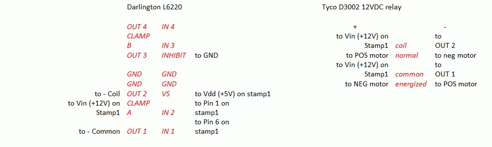
I am trying to simply run a 12VDC motor (max load 1.3A - in stall) in both directions using a BS1.· I have a darlington array (L6220) and a Tyco 12V relay (D3002), and a 12VDC 2A power supply.· I have wired it as shown below.·· The program is also below.· Once the relay is energized I start getting flakey results.·Ie. fwd when it should reverse, pulse fwd insteead of rev, pulse fwd several times, etc...· I have tried shorting OUT1 to OUT4 and IN1 to IN4 to double the motor channel, but the results were the same.· I have also tried this using a BS2 with no better results, so went back to my BS1.
Has anyone successfully gotten a DC motor to run in both directions without the stamp motor controller?
Thanks in advance!
Kristen
ps. I'm a mechanical engineer, so please be patient!

·
DO:
DEBUG "on fwd", CR
HIGH 6
DEBUG PIN6, CR
DEBUG PIN1, CR
PAUSE 2000
DEBUG "off", CR
LOW 6
PAUSE 2000
DEBUG "rev", CR
LOW 1
HIGH 6
DEBUG PIN6, CR
DEBUG PIN1, CR
PAUSE 2000
DEBUG "off ", CR
LOW 6
HIGH 1
PAUSE 2000
GOTO DO
I am trying to simply run a 12VDC motor (max load 1.3A - in stall) in both directions using a BS1.· I have a darlington array (L6220) and a Tyco 12V relay (D3002), and a 12VDC 2A power supply.· I have wired it as shown below.·· The program is also below.· Once the relay is energized I start getting flakey results.·Ie. fwd when it should reverse, pulse fwd insteead of rev, pulse fwd several times, etc...· I have tried shorting OUT1 to OUT4 and IN1 to IN4 to double the motor channel, but the results were the same.· I have also tried this using a BS2 with no better results, so went back to my BS1.
Has anyone successfully gotten a DC motor to run in both directions without the stamp motor controller?
Thanks in advance!
Kristen
ps. I'm a mechanical engineer, so please be patient!
·
DO:
DEBUG "on fwd", CR
HIGH 6
DEBUG PIN6, CR
DEBUG PIN1, CR
PAUSE 2000
DEBUG "off", CR
LOW 6
PAUSE 2000
DEBUG "rev", CR
LOW 1
HIGH 6
DEBUG PIN6, CR
DEBUG PIN1, CR
PAUSE 2000
DEBUG "off ", CR
LOW 6
HIGH 1
PAUSE 2000
GOTO DO
992 x 298 - 9K
Comments
That's a pretty good sized motor! I'm sure you can drive it though. Is the motor verified good? I mean, wire the motor directly to the same power supply you plan to use in your circuit. That'd be a good check to see if the supply sags on startup and check the motor.
Lastly, I'd run the BS off a completely separate supply while your are building the system. A battery would work, or a separate wall wart. A battery would probably be safer in case your wall wart is not a clean DC supply. Only tie the battery ground and the 12V supply grounds together. That way you are insured that the control (BS) ALWAYS has power...... if the 12V supply sags when you spin up the motor, it CAN reset the BS. Believe me, you'll chase your tail finding that problem! [noparse]:)[/noparse] Later down the road, if you want to run it all off the 12V supply you can...... but get it working FIRST!
I hope some of this helps,
▔▔▔▔▔▔▔▔▔▔▔▔▔▔▔▔▔▔▔▔▔▔▔▔
"puff"...... Smile, there went another one.
I tried taking baby steps as follows:
0.·· Ran the DC motor (12VDC) directly from power supply.
1.······I successfully ran the motor (12VDC) with the array using out 1 and out 2
2.······ Then wired normal and common on relay (as shown) and ran motor successfully using IN 1.
3.······ Then wired coil on relay (as shown) and used it to stop/start motor successfully using IN 1 and IN 2.
4.······ Wired energized (as shown) and tried to run in direction 1, stop, direction 2, stop, etc…· and we’re back to flakey results….works for a bit then starts yielding flakey results, will work again, then flakey again, etc…
5.· Shorted OUT1 and OUT 4 and IN1 and IN4 to double the motor channel, no change in results.
6.· Tried all the above with a BS2, using pin5 and pin 15 - no change in results.
I'm now in the process of repeating all the above steps with a 13.8VDC, 15A power supply to make sure it isn't a power spike/sag as you mentioned.
Thanks for your help!!
Kristen
As the motor is probably the type with brushes, it may generate
a lot of "noise"when the brushes jump over the collector and arc.
So you might want to consider putting some large ceramic capacitors
over the motor.
Also you don't seem to have a diode over the coil of the relay.
When a relay (coil) switches off the coil is still charged with magnetic
energy and it will generate a big negative voltage peak.
So you might want to put a big diode over the relais with the cathode on
the +12v and the anode at the ground.
The same goes for the motor, when suddenly the voltage is removed
with a relay it might generate a big negative voltage puls. Which might
produces arcs over the contacts of the relay, so before the relay you
might want to place a big diode.
Also when a big motor starts it might consume 3-5 times as much current
as during normal operation.
So you might want to have a biggish capacitor over the stamp to maintain
voltage over the stamp.
To prevent dropping of the voltage over capacitor you might want to consider
feeding the capacitor through a coil or diode.
If you would feed the capacitor through a diode then the motor can't
discharge the capacitor if the voltage drops for a fraction but the stamp
is still ensured of a clean voltage.
greetings Arend-Paul Spijkerman
basic stamp scope
wiresalot