

How do I convert this truth table into a Prop-compatible chip or logic circuit?
 ElectricAye
Posts: 4,561
ElectricAye
Posts: 4,561
Good morning,
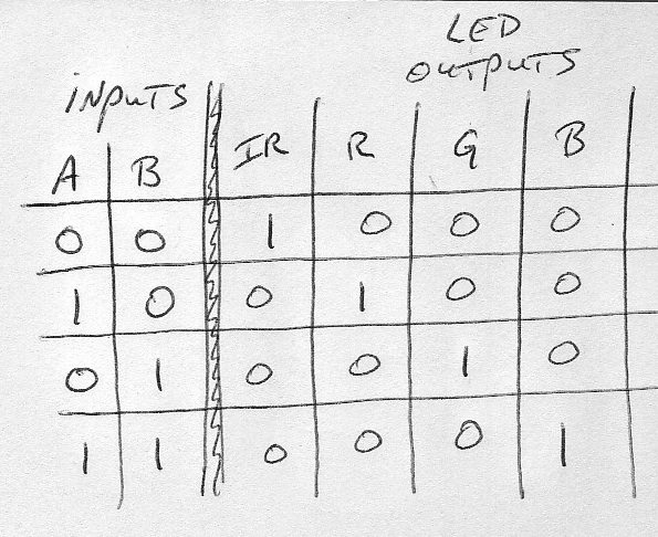
I would like to independently control 4 LEDS but I can budget only 2 Prop pins to do so. I've been trying to reinvent the wheel on this with NAND gates and XOR's etc, but I just can't figure it out and I'm sure there's some kind of simple Prop-compatible (counting?) chip that can easily do this. But what da heck is it?
Suggestions will be greatly appreciated.
Truth table is attached.
595 x 486 - 130K
Comments
Is the challenge to do this with one chip?
If you really want active high outputs, I think a 74HC4051 can do it with one chip. (or 4051). Feed in a high and it passes it through to one of the outputs. Though 'low' would be tristate. Won't matter if driving leds.
Active low driving leds won't matter either - the aim is just to get the led to light up.
138 or 139 if you have them in the parts drawer.
▔▔▔▔▔▔▔▔▔▔▔▔▔▔▔▔▔▔▔▔▔▔▔▔
www.smarthome.viviti.com/propeller
Post Edited (Dr_Acula) : 6/18/2010 2:35:30 PM GMT
Doing this with one chip would be nice but I'd settle for almost any combo of gates right now. I'll have a look at your above suggestions.
thanks, Doc
If two chips, you can do pretty much any logic with, say, an AND gate and hex inverters eg 74HC08 and 74HC04. Use the 4 AND gates and invert one or both of the inputs for each output state.
▔▔▔▔▔▔▔▔▔▔▔▔▔▔▔▔▔▔▔▔▔▔▔▔
www.smarthome.viviti.com/propeller
http://focus.ti.com/lit/ds/symlink/cd74act139.pdf
YOu could use this chip, or copy the logic diagram...
▔▔▔▔▔▔▔▔▔▔▔▔▔▔▔▔▔▔▔▔▔▔▔▔
My Prop Apps:· http://www.rayslogic.com/propeller/Programming/Programming.htm
My Prop Info: ·http://www.rayslogic.com/propeller/propeller.htm
My Prop Products:· http://www.rayslogic.com/Propeller/Products/Products.htm
NOT a AND NOT b· -> IR 1
a AND NOT b -> R 1
NOT a AND b -> G 1
a AND b· -> B 1
this is excellent. It seems like somebody told me years ago: you can design any logic circuit with enough NAND gates. As a point of pride, I took it upon myself to design this from scratch... but simply choked on it.
Thanks for helping me out today.
Look at this image and think about how many states are represented.
It is a little more complicated than the 2 variable diagram.
Just count the number of color spaces. Don't forget the area where there is no color.
Use English to describe the conditions for each color "space". Don't use set theory, just logic.
Once you have a list of statements, translate them to equations.
That's just one way to design a 1 of 8 decoder from scratch with confidence.
Cheers,
--Steve
▔▔▔▔▔▔▔▔▔▔▔▔▔▔▔▔▔▔▔▔▔▔▔▔
Propeller Pages: Propeller JVM
Post Edited (jazzed) : 6/18/2010 4:45:43 PM GMT
I'll post a circuit later, but I was able to get this functionality with 4 transistors, 2 diodes, and 5 resistors.
▔▔▔▔▔▔▔▔▔▔▔▔▔▔▔▔▔▔▔▔▔▔▔▔
Beau Schwabe
IC Layout Engineer
Parallax, Inc.
Post Edited (Beau Schwabe (Parallax)) : 6/18/2010 7:00:53 PM GMT
▔▔▔▔▔▔▔▔▔▔▔▔▔▔▔▔▔▔▔▔▔▔▔▔
cmapspublic3.ihmc.us:80/servlet/SBReadResourceServlet?rid=1181572927203_421963583_5511&partName=htmltext
Hello Rest Of The World
Hello Debris
Install a propeller and blow them away
I was sure i posted an answer here. But i don't see it.
Hope this one works.
ww1.microchip.com/downloads/en/appnotes/00234a.pdf
Page 2. Fig 4
Good look
Regards
▔▔▔▔▔▔▔▔▔▔▔▔▔▔▔▔▔▔▔▔▔▔▔▔
Are you looking for a professional PCB/Schematichs software?
Kicad: GPL. You can do Schematics, PCBS, Gerber interfaces, 3d-views and more
www.lis.inpg.fr/realise_au_lis/kicad/
Search in Parallax Forums Using Google
www.google.com/advanced_search?q=+site:forums.parallax.com&num=20&hl=en&lr=
▔▔▔▔▔▔▔▔▔▔▔▔▔▔▔▔▔▔▔▔▔▔▔▔
Beau Schwabe
IC Layout Engineer
Parallax, Inc.
Yes, it was this:
http://forums.parallax.com/showthread.php?p=910828
But then somebody mentioned that perhaps some little bit of current might flow through both LEDs??? and that might emit a little bit of light from the undesired LED???? See...
I'm not sure if that's true for what I wanted to do and, if so, whether or not it would mess up my measurements, so I decided to be chicken and use 2 pins to drive 4 LEDs using pure Spock logic.
EDIT: added Peter's quote.
Post Edited (ElectricAye) : 6/18/2010 9:07:13 PM GMT
Man, are you trying to fry my brain?
@Beau
I always love the discrete logic solutions. I am trying to get more proficient with such things. But alas, I find my endeavors are in vain. When I am laying out my PCBs I find the parts for discrete logic circuits are almost never as small as some IC I can find on the market that also can do the same thing at higher frequencies , use less power while doing it, and ultimately are cheaper (after the cost of PCB sqaurefootage and more assembly costs). I will not be downtroddened; exercising your brain in new and exciting ways will keep you forever young.
▔▔▔▔▔▔▔▔▔▔▔▔▔▔▔▔▔▔▔▔▔▔▔▔
April, 2008: when I discovered the answers to all my micro-computational-botherations!
Some of my objects:
MCP3X0X ADC Driver - Programmable Schmitt inputs, frequency reading, and more!
Simple Propeller-based Database - Making life easier and more readable for all your EEPROM storage needs.
String Manipulation Library - Don't allow strings to be the bane of the Propeller, bend them to your will!
Fast Inter-Propeller Comm - Fast communication between two propellers (1.37MB/s @100MHz)!
▔▔▔▔▔▔▔▔▔▔▔▔▔▔▔▔▔▔▔▔▔▔▔▔
cmapspublic3.ihmc.us:80/servlet/SBReadResourceServlet?rid=1181572927203_421963583_5511&partName=htmltext
Hello Rest Of The World
Hello Debris
Install a propeller and blow them away
I guess just for the intellectual challenge, see below for a solution using just NAND.
This would be 3 chips to replicate your logic. But if you want to light up a led, use active low and that saves the 4 output inverters, and so now it would only be two chips.
I do like Beau's transistor solution.
▔▔▔▔▔▔▔▔▔▔▔▔▔▔▔▔▔▔▔▔▔▔▔▔
www.smarthome.viviti.com/propeller
http://www.allaboutcircuits.com/vol_4/chpt_8/6.html
http://en.wikipedia.org/wiki/Karnaugh_maps
▔▔▔▔▔▔▔▔▔▔▔▔▔▔▔▔▔▔▔▔▔▔▔▔
It's all a function of time.
That's very impressive. No wonder I couldn't figure it out by myself. That fries my brain, too.
The right NAND gate has both inputs tied together.·This makes it a NOT gate...
That along with the NAND gate to its left makes the combined two NAND gates function as an AND gate (clever use of the NAND gates).
▔▔▔▔▔▔▔▔▔▔▔▔▔▔▔▔▔▔▔▔▔▔▔▔
Composite NTSC sprite driver: Forum
NTSC & PAL driver templates: ObEx Forum
OnePinTVText driver: ObEx Forum
joshblog.net/projects/logic-gate-simulator/Logicly.html
... you can knock two of the NAND gates off of Dr_Acula schematic by combining the inverter function of two of the input NANDs.
▔▔▔▔▔▔▔▔▔▔▔▔▔▔▔▔▔▔▔▔▔▔▔▔
Beau Schwabe
IC Layout Engineer
Parallax, Inc.