How to Wire Circuits from Schematics
How to Wire Circuits from Schematics
··
In electronics, the schematic is a drawing that represents a circuit, and is used to communicate designs and ideas. Knowing how to draw and read a schematic is very important as you venture into the world of electronics, particularly if you want to share your design with fellow electronic enthusiasts or if you want to use a circuit designed by someone else.
·
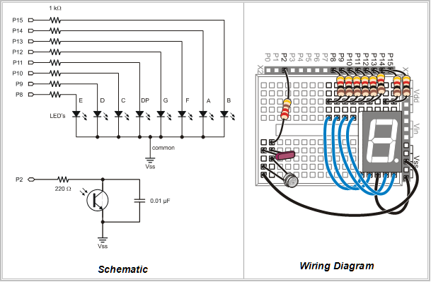
If you have gone through any of our Stamps in Class texts, you’ve probably come across various schematics and wiring diagrams showing you how to build the circuits needed for your program to run. Until now you may have relied solely on the wiring diagram, or the picture that shows you exactly which breadboard sockets to connect your electronic components to. However, in the “real world” of electronics, wiring diagrams aren’t generally used to portray circuits; so you’ll have to learn how to read the schematic instead.
·
·
At first glance, a schematic might seem somewhat daunting, and you might be confused by all of the symbols and lines. But have faith! Even the most complex schematics can be easily wired if broken into small pieces. Today, we’ll get you up to speed on how to read schematics, and how to wire circuits from them on a breadboard.·To get started, just click here!
▔▔▔▔▔▔▔▔▔▔▔▔▔▔▔▔▔▔▔▔▔▔▔▔
Jessica Uelmen
Education Department
Parallax Inc.
Post Edited (Jessica Uelmen (Parallax)) : 8/25/2010 6:32:51 PM GMT


Comments
▔▔▔▔▔▔▔▔▔▔▔▔▔▔▔▔▔▔▔▔▔▔▔▔
Deus tantum me iudicabit
For wiring, would you start from left to right from the schematics?
Or simply put the most important part first and then hook up the rest?
From a newbie, what would be a GOOD RULE OF THUMB to start and expand?
I personnaly tend to connect the stamp pins first, then follow that pin until the end...
But sometimes many pins is required and tend to skip a pin by mistake...
CHeers
Yosh...
One key thing I do -- write a check on the schematic by each wire as I install it. One last thing you can do -- use an ohm-meter to check that each wire goes where it's supposed to go writing a SECOND check-mark on the schematic to show it's been ohmed-out.
My motto in all things electronic.
I too wire GND first then Power and then SIGs and I hilight the connection on the shematic too.
Peter KG6LSE
▔▔▔▔▔▔▔▔▔▔▔▔▔▔▔▔▔▔▔▔▔▔▔▔
"Carpe Ducktum" "seize the tape!!"
peterthethinker.com/tesla/Venom/Venom.html
Never underestimate the bandwidth of a station wagon full of tapes hurtling down the highway. —Tanenbaum, Andrew S.
LOL
Post Edited (Peter KG6LSE) : 6/1/2010 5:31:43 AM GMT
Ok... great. Just need to make it a habit !
Cheers
Yosh