

What's wrong with my PCB? [re-resolved]
 mpark
Posts: 1,336
mpark
Posts: 1,336
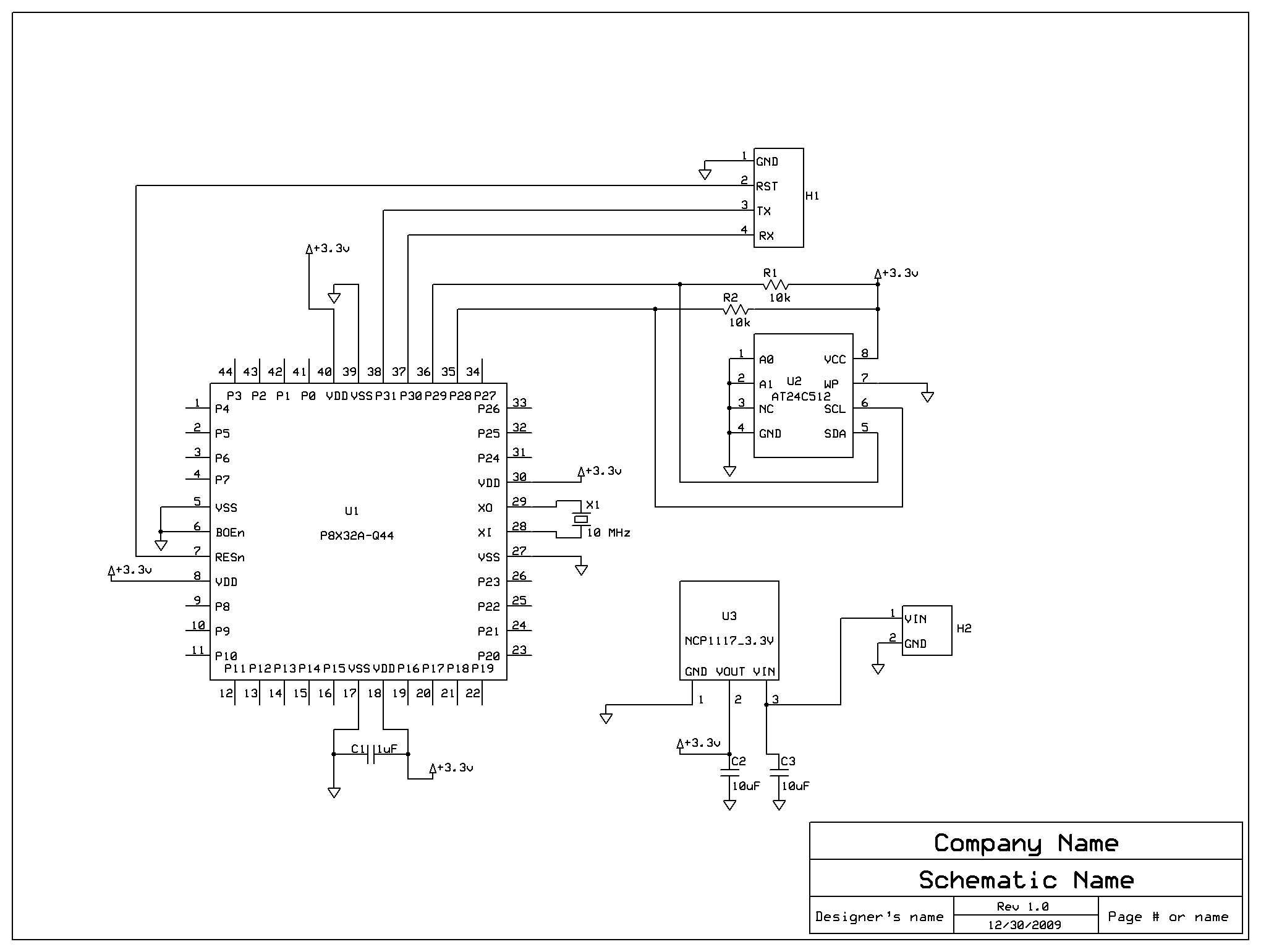
I made these little PCBs for the QFP Prop, but I must have messed something up. I've assembled a bunch but more than half seem to have bad PLLs.
I first put on the voltage regulator and caps and verify that it puts out 3.3V (nominal; it's always a bit less). Then I solder on the Prop chip and crystal and check continuity on all pins with my meter. I am soldering by hand, btw.
Then I download a little test program. Distressingly often, the test only runs if I comment out the clock mode and crystal settings, which is why I assume the PLL is bad. (If the test passes with the crystal I proceed to add the EEPROM and resistors.)
On my last batch I added 0.1uF bypass caps but they didn't help.
I have a terrible track record with hardware, so it's quite possible the PLL failures are caused by me, but just in case there's a problem in the schematic or layout, I'd be grateful if someone could point it out.
EDIT: The PLLs are not failing. Replacing the little watch crystals with regular crystals makes everything OK, at least so far.
EDIT: It wasn't the crystals themselves, it was flux between the pins.
Post Edited (mpark) : 4/9/2010 4:49:06 AM GMT
2040 x 1540 - 12K
605 x 474 - 32K
649 x 486 - 23K
Comments
propeller.wikispaces.com/pcbdesign
Check that all the Vss and Vdd pins are properly soldered.
The regulator capacitors should meet the ESR spec.
▔▔▔▔▔▔▔▔▔▔▔▔▔▔▔▔▔▔▔▔▔▔▔▔
Leon Heller
Amateur radio callsign: G1HSM
Post Edited (Leon) : 4/7/2010 10:48:49 PM GMT
I don't know if that has anything to do with the problem, I just thought I would point it out.
Bean
▔▔▔▔▔▔▔▔▔▔▔▔▔▔▔▔▔▔▔▔▔▔▔▔
- - - - - - - - - - - - - - - - - - - - - - - - - - - - - - -
Use BASIC on the Propeller with the speed of assembly language.
PropBASIC thread http://forums.parallax.com/showthread.php?p=867134
March 2010 Nuts and Volts article·http://www.parallax.com/Portals/0/Downloads/docs/cols/nv/prop/col/nvp5.pdf
- - - - - - - - - - - - - - - - - - - - - - - - - - - - - - -
There are two rules in life:
· 1) Never divulge all information
BTW, as ong as you have a sound layout with adequate bypassing, a 10 MHz crystal should work without a problem.
-Phil
(I did add caps to the other two Vdd-Vss pairs, as I mentioned.)
▔▔▔▔▔▔▔▔▔▔▔▔▔▔▔▔▔▔▔▔▔▔▔▔
Leon Heller
Amateur radio callsign: G1HSM
What's the part number for your crystal?
Also, if you're trying to run at 16X, you'll be lucky if just the first cog works. Definitely won't work with 2 cogs.
▔▔▔▔▔▔▔▔▔▔▔▔▔▔▔▔▔▔▔▔▔▔▔▔
My Prop Info&Apps: ·http://www.rayslogic.com/propeller/propeller.htm
My Prop Products:· http://www.rayslogic.com/Propeller/Products/Products.htm
I think if you're providing as much capacitance as the Protoboard, you should be fine.
▔▔▔▔▔▔▔▔▔▔▔▔▔▔▔▔▔▔▔▔▔▔▔▔
Propeller Forums RSS Feed!
Gadget Gangster - Share your Electronic Projects
▔▔▔▔▔▔▔▔▔▔▔▔▔▔▔▔▔▔▔▔▔▔▔▔
Check out my brand new site.
I'm using the 10MHz but only at 8x.
I do put all the caps in before applying power. I'll try squeezing in a couple more decoupling caps.
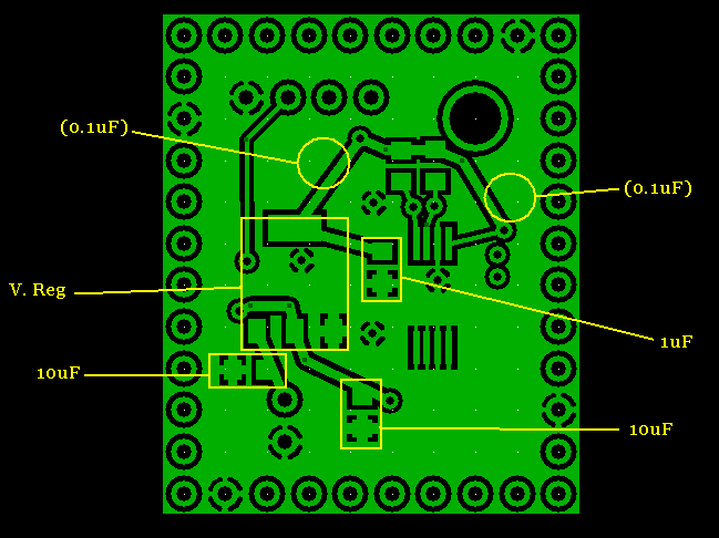
I cannot stress enough the importance of decoupling caps. They are mandatory at each set of power pins. I know the PPB only has 2 x 1uF. It is important that the power pins of the prop are joined like a power plane also. Michael, take a look at the RamBlade I sent you.
BTW I have 13.5MHz * 8 working. I just have not done enough testing to be assured I can run it without problems.
▔▔▔▔▔▔▔▔▔▔▔▔▔▔▔▔▔▔▔▔▔▔▔▔
Links to other interesting threads:
· Home of the MultiBladeProps: TriBlade,·RamBlade,·SixBlade, website
· Single Board Computer:·3 Propeller ICs·and a·TriBladeProp board (ZiCog Z80 Emulator)
· Prop Tools under Development or Completed (Index)
· Emulators: CPUs Z80 etc; Micros Altair etc;· Terminals·VT100 etc; (Index) ZiCog (Z80) , MoCog (6809)·
· Prop OS: SphinxOS·, PropDos , PropCmd··· Search the Propeller forums·(uses advanced Google search)
My cruising website is: ·www.bluemagic.biz·· MultiBlade Props: www.cluso.bluemagic.biz
-Phil
Post Edited (Phil Pilgrim (PhiPi)) : 4/8/2010 3:53:27 AM GMT
BTW: Vdd, An .. An+7, Vss is a more "standard" Propeller pinout for headers than Vdd, Vss, An .. An+7.
-Phil
When it comes to capacitors bigger is not better, you have a value of 1uf for the decouplers, what type are these? Use monolithic ceramic 0.1uF for these as the lower values have a lower impedance at high frequencies which is where they are needed.
I am also assuming you are running from a power source that can provide the current required when you run at a higher frequency, don't use 9V batteries, they are the worst power source every invented. Go for some AAs or just use a power pack.
As regards the watch crystals I hope you have it laying down as the things are rather delicate. As a rule try to lay every component flat against the board, anything that can get knocked and bent will be.
▔▔▔▔▔▔▔▔▔▔▔▔▔▔▔▔▔▔▔▔▔▔▔▔
*Peter*
I'm afraid I haven't paid much attention to the type of caps I use. I assume they're all ceramic. I started with a single 1uF for decoupling 'cuz that's what the Schmartboard prop board uses (the two 10uF guys are for the voltage regulator). I've stuck on a couple 0.1uF and tomorrow I'll try adding a couple more 0.1uF caps. Do you think I should remove the 1uF cap once I have the four 0.1uF guys in?
I am using a wall wart from Parallax so I'm sure there's plenty of current.
I appreciate everyone's feedback so far. Tomorrow I hope to try out some things.
▔▔▔▔▔▔▔▔▔▔▔▔▔▔▔▔▔▔▔▔▔▔▔▔
*Peter*
I see what you mean with the Protoboard layout. The "standard" I was referring to was the Demo Board header and the DB Expander pinout, both of which use the Vdd, A[noparse][[/noparse]n] .. A[noparse][[/noparse]n+7], Vss order, along with the pinout of the 40-pin DIP and PropStick USB (by adding Vdd or Vss pins beyond the ends of the package).
So I guess pick the one that seems the more useful for your app.
-Phil
▔▔▔▔▔▔▔▔▔▔▔▔▔▔▔▔▔▔▔▔▔▔▔▔
Visit some of my articles at Propeller Wiki:
MATH on the propeller propeller.wikispaces.com/MATH
pPropQL: propeller.wikispaces.com/pPropQL
pPropQL020: propeller.wikispaces.com/pPropQL020
OMU for the pPropQL/020 propeller.wikispaces.com/OMU
pPropellerSim - A propeller simulator for ASM development sourceforge.net/projects/ppropellersim
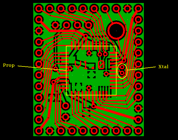
I we be track this thread from start and are surprised that anyone have not mentioned That You have to small space between signal/Power traces and Traces/Vias to XTal.
You must always think as XTal are small signal analog device very sensitive to transients on its Traces - And that require careful Routing around them to WORK correctly.
Regards
Christoffer J
▔▔▔▔▔▔▔▔▔▔▔▔▔▔▔▔▔▔▔▔▔▔▔▔
Nothing is impossible, there are only different degrees of difficulty.
For every stupid question there is at least one intelligent answer.
Don't guess - ask instead.
If you don't ask you won't know.
If your gonna construct something, make it·as simple as·possible yet as versatile as posible.
Sapieha
@Michael, did you try another crystal? Have you checked the supply voltages? Maybe a photo will help.
▔▔▔▔▔▔▔▔▔▔▔▔▔▔▔▔▔▔▔▔▔▔▔▔
*Peter*
I agree - But it is some things He can improve around XTals via's - That need some careful skills to handle knife.
After soldering XTal he need klear with knife spaces between via's to XTal and other traces to have as big space between them as posible.
Regards
▔▔▔▔▔▔▔▔▔▔▔▔▔▔▔▔▔▔▔▔▔▔▔▔
Nothing is impossible, there are only different degrees of difficulty.
For every stupid question there is at least one intelligent answer.
Don't guess - ask instead.
If you don't ask you won't know.
If your gonna construct something, make it·as simple as·possible yet as versatile as posible.
Sapieha
If you're okay there, I guess I'd suspect the crystal. Maybe there's an open or short. You might try pulling the prop off and testing it with another xtal, or jury rigging another xtal on to see if you can get it to work.
fwiw
▔▔▔▔▔▔▔▔▔▔▔▔▔▔▔▔▔▔▔▔▔▔▔▔
Propeller Forums RSS Feed!
Gadget Gangster - Share your Electronic Projects
▔▔▔▔▔▔▔▔▔▔▔▔▔▔▔▔▔▔▔▔▔▔▔▔
My Prop Info&Apps: ·http://www.rayslogic.com/propeller/propeller.htm
My Prop Products:· http://www.rayslogic.com/Propeller/Products/Products.htm
gb.mouser.com/search/ProductDetail.aspx?qs=6siQ5y5nVCyQVMHsj0Ua5w==
It's 18pF. That might possibly cause a problem at 10 MHz as the oscillator is out of spec. at that frequency.
▔▔▔▔▔▔▔▔▔▔▔▔▔▔▔▔▔▔▔▔▔▔▔▔
Leon Heller
Amateur radio callsign: G1HSM
Post Edited (Leon) : 4/8/2010 1:47:05 PM GMT
Only big difference may be "drive level" which is 5X bigger for mine.
Anyway, since I've not seen anybody using this type of crystal before with the Prop, I would bet that's the problem.
▔▔▔▔▔▔▔▔▔▔▔▔▔▔▔▔▔▔▔▔▔▔▔▔
My Prop Info&Apps: ·http://www.rayslogic.com/propeller/propeller.htm
My Prop Products:· http://www.rayslogic.com/Propeller/Products/Products.htm
Peter Jakacki, haven't you had good luck with the little 10MHz Citizen crystals, or was it just the 5MHz?
Sapieha, see attached drawing. Are you suggesting I trim away the pink portions of the copper, top and bottom?
1) Your Vdd inputs seem sort of strung out - If you look at the back of a proto-board you'll notice the power plane is very even and close to the Vdd inputs. They also have allot of foil feeding them. Bypass caps should also have a solid ground - use the 'solid' connection to the ground plane not the 'thermal' in Express PCB.
2) As a general guideline, you'd like your decoupling caps as close to the Vdd inputs as you can get.
3) Echoing an earlier comment, your crystal trace lines could use some breathing room.
4) There is just a whole lot going on in a very small space there. Any chance you could spread it out a bit?
I know this is not helping on you current run of boards. One thing you might try with this design is to put a pretty beefy wire between the regulator tab output and pin output to make sure those are balanced at startup.
I feel your pain, I've experienced similar problems with boards - I solved it with bigger ground planes and power delivery from a single point directly under the prop.
Jim-
▔▔▔▔▔▔▔▔▔▔▔▔▔▔▔▔▔▔▔▔▔▔▔▔
Signature space for rent!
Send $1 to CannibalRobotics.com.