

M.P.P.T. - what is all this talk about anyway?
 Beau Schwabe
Posts: 6,576
Beau Schwabe
Posts: 6,576
I thought I would add my own 2 cents about how I understand MPPT since there has been a lot of talk about it lately.
Perhaps even this could be a proposal for a mini design contest for the most efficient MPPT design from our forum members? A FREE Prop Proto Board + Parts Kit to the winner? Ken Gracey are you on board with this?

▔▔▔▔▔▔▔▔▔▔▔▔▔▔▔▔▔▔▔▔▔▔▔▔
Beau Schwabe
IC Layout Engineer
Parallax, Inc.
Perhaps even this could be a proposal for a mini design contest for the most efficient MPPT design from our forum members? A FREE Prop Proto Board + Parts Kit to the winner? Ken Gracey are you on board with this?
▔▔▔▔▔▔▔▔▔▔▔▔▔▔▔▔▔▔▔▔▔▔▔▔
Beau Schwabe
IC Layout Engineer
Parallax, Inc.
1099 x 767 - 264K
Comments
▔▔▔▔▔▔▔▔▔▔▔▔▔▔▔▔▔▔▔▔▔▔▔▔
Ken Gracey
Parallax Inc.
Follow me at http://twitter.com/ParallaxKen for some insider news.
FREE Prop Proto Board
Parts Kit
and a Solar Cell 6 Pack
▔▔▔▔▔▔▔▔▔▔▔▔▔▔▔▔▔▔▔▔▔▔▔▔
Beau Schwabe
IC Layout Engineer
Parallax, Inc.
-Phil
I think I get what you are saying, lets see an idea proposal with a little more detail of what you describe.
▔▔▔▔▔▔▔▔▔▔▔▔▔▔▔▔▔▔▔▔▔▔▔▔
Beau Schwabe
IC Layout Engineer
Parallax, Inc.
I guess another way of putting it is this: Given the above MPP, if I attach a constant current load of 4A to the PV array (not caring what the voltage is or, hence, the equivalent load resistance), will the output voltage automatically migrate to 3V? Or is there more that I have to do to manipulate it to operate at its MPP?
-Phil
Update: Now that I think about it, it's a pretty silly question. If the OPP is 4A @ 3V, and I draw 4A, the output will be 3V.
Post Edited (Phil Pilgrim (PhiPi)) : 3/12/2010 6:47:41 AM GMT
If so, include peltier?
▔▔▔▔▔▔▔▔▔▔▔▔▔▔▔▔▔▔▔▔▔▔▔▔
TERMS OF USE: MIT License
"Permission is hereby granted, free of charge, to any pers...........................
..............................OMITTED FOR FORUM...............................................
.................. OF OR IN CONNECTION WITH THE SOFTWARE OR THE USE OR OTHER DEALINGS IN THE SOFTWARE. "
The dsp/fpga king is dead, long live the prop.
-Phil
Keep in mind also since solar is always on the move (i.e. time of day, clouds, etc.), it becomes necessary to track where the maximum power is under any condition.
To complicate things, not only does the panel voltage change, but so does the internal resistance (Rsol)
So regardless if you have a DC-DC converter (as your load) or just powering a device directly, you still have a similar problem when you assume that the power is 'fixed'.
What needs to happen in a MPPT is a way to dynamically measure the 'unloaded' voltage, and then 'adjust' the voltage across Rload so that it is exactly half of the unloaded panel voltage. This way even if Rload changes due to other demands (i.e. a DC-DC converter), the MPPT tracking mechanism will dynamically adjust to keep Rload constant with respect to the immediate available power from the panel.
Clock Loop,
Yes, the backsides do get warm, but I don't think this is a cost effective solution when using peltier devices. There are "hybrid' Solar panels out there, but they are designed to heat water and provide PV. ...and I think the 'fluid' is actually passed in front of the PV cells utilizing the dark color of the PV cells to transfer thermal heat to the fluid.
▔▔▔▔▔▔▔▔▔▔▔▔▔▔▔▔▔▔▔▔▔▔▔▔
Beau Schwabe
IC Layout Engineer
Parallax, Inc.
Post Edited (Beau Schwabe (Parallax)) : 3/12/2010 4:14:37 PM GMT
I'm in.
I'll have to do some experiments.
Do I have to use the parallax solar panel ? I already have 6 from harbor freight (15W each).
Bean
▔▔▔▔▔▔▔▔▔▔▔▔▔▔▔▔▔▔▔▔▔▔▔▔
- - - - - - - - - - - - - - - - - - - - - - - - - - - - - - -
Use BASIC on the Propeller with the speed of assembly language.
PropBASIC thread http://forums.parallax.com/showthread.php?p=867134
March 2010 Nuts and Volts article·http://www.parallax.com/Portals/0/Downloads/docs/cols/nv/prop/col/nvp5.pdf
·
No, you can use your own panels, but you may get bonus points from the judges for using Parallax products for the remainder of your design.
We are still working out the contest details, expect something officially posted soon.
▔▔▔▔▔▔▔▔▔▔▔▔▔▔▔▔▔▔▔▔▔▔▔▔
Beau Schwabe
IC Layout Engineer
Parallax, Inc.
But this is for a DC-DC converter that's supplying a constant load. If the objective is to provide as much current as possible at a fixed voltage (e.g. a charge controller), the question changes a little. If the charge controller asks for more power than is available from the PV array, will this force the PV array into a sub-optimal voltage/current combination? In other words, could the charge controller get more power by asking for less? If so, it then becomes incumbent on the charge controller to reduce its power demand until the sweet spot is reattained. If the power vs. current curve is monomodal, a hill-climbing algorithm would suffice, without having to interrupt the load to measure the open-circuit voltage.
-Phil
Here's where my ignorance of charge controllers becomes painfully manifest. Suppose I want to charge a 12V battery. What's it take? 13-some volts to start? Or do I just regulate the charging current until the voltage reaches a certain level? In any event, I need to place a current demand on the PV array. And the more current I demand, the lower the voltage I will see on the DC-DC converter's input. Right? But I can monitor both the input voltage and current and jiggle the input current requirements a little on either side of my operating point by varying the output regulation. By doing so, I can compute the direction of the gradient of the power vs. current curve at my operating point. Having done so, I can then move the operating point in the direction of the gradient to increase the power input.
But I may have to do so at the expense of charge current, and this may have an adverse effect on how efficiently I can get energy into the battery. Rather than a steady-state charge, maybe it makes more sense to store the energy in a large cap until it reaches some critical voltage, then pulse charge the battery at intervals from the cap.
I'm betting there's more to this charging business than just maximizing power from the PV array. You also have to consider the optimum V/I operating point for getting energy into the battery, and that complicates things.
-Phil
From what I've read if you are charging batteries you just adjust the PWM·duty cycle·until you get the most current going into the battery.
You really don't have to worry about voltage because maximum charge is when maximum current is going in.
For other loads you may have to measure both current and voltage, but I don't think you do when charging batteries.
Using Beau's example in the top post, let's say that Rload is 5 Ohms. But we need the solar panel to "see" 15 ohms for maximum power.
You would run the solar panel output into a capacitor, then use a PWM circuit with a 1/3 duty cycle to draw power from the capacitor.
Now the panel "experience" a 15 ohm load (on average). And you will get much more power to the load than if you connected the panel directly.
At least this is my understanding. And that is assuming you don't need to boost the panel voltage.
P.S. I could be wrong...But I doubt it.... I thought I was wrong once.... But I was mistaken.·
Bean.
▔▔▔▔▔▔▔▔▔▔▔▔▔▔▔▔▔▔▔▔▔▔▔▔
- - - - - - - - - - - - - - - - - - - - - - - - - - - - - - -
Use BASIC on the Propeller with the speed of assembly language.
PropBASIC thread http://forums.parallax.com/showthread.php?p=867134
March 2010 Nuts and Volts article·http://www.parallax.com/Portals/0/Downloads/docs/cols/nv/prop/col/nvp5.pdf
Post Edited (Bean) : 3/13/2010 1:47:21 AM GMT
I agreed with Bean, but then he mistook himself and so I thought Id better not. No, really there are several ways to do this and hence the reason for the contest.
Here is more in answer to your questions though...
Battery charging greatly depends on the chemistry of the battery, and I always refer to the battery manufacturer for their recommended charging curve. For SLA (Sealed Lead Acid) batteries 13V is about the absolute minimum (2.16V per cell) however they would be much happier at 14.4V (2.4V per cell).
There are several charge designs out there ranging in complexity and are usually proportional to how quickly you want the battery charged.
One of my favorite approaches and one I feel is most complete is a 3-phase charger. In the first phase you apply a constant current until a certain voltage is achieved. In the second Phase you apply a constant voltage until the current drops off to a certain level. In the third Phase you switch to an indefinite float charge until the battery is ready to be used.
With a supply of 14.4V you don't have much voltage overhead for a constant current Phase unless your design has very little IR drop, but you can do a constant voltage charge followed by a float charge without much problem.
"...In any event, I need to place a current demand on the PV array. And the more current I demand, the lower the voltage I will see on the DC-DC converter's input. Right?..." - Yes, this is correct, but if the DC-DC converter is integrated as part of the MPPT and the input to the DC-DC converter section is kept right at MPP your at the best possible outcome scenario.
"...But I may have to do so at the expense of charge current..." - Yes, to gain any ground here, you simply need more overhead voltage, and you may be able to create a charge pump using a capacitor to periodically dump large current into the battery, but the average current over time using this method will not have any real net gain.
"...I'm betting there's more to this charging business than just maximizing power from the PV array..." - Maximizing the power is a large portion of it.
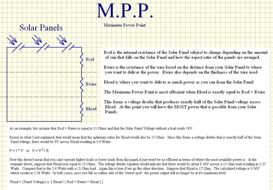
To continue with the example I gave at the beginning of this thread... If I have a Solar panel that reads 18V without a load and Rsol+Rwire is equal to 15 Ohms, then my MPP is 9V 5.4 Watts under a 15 Ohms load.
If I wanted to charge a 12V battery at constant voltage of 14V with this Solar Panel, I would need to adjust the equivalent load resistance to 52.5 Ohms. This equates to a charging current of 266mA or 3.73 Watts meaning that the Panel is only operating at about 70% of it's total capacity.
By using a DC-DC converter with a better than 70% conversion efficiency, you can narrow the inefficiency gap and allow your solar panel to work more effectively.
For example if the DC-DC converter is 85% efficient (which is actually pretty low) then the available 5.4 MPP Watts becomes 4.59 Watts (5.4W X 85% = 4.59W)
4.59W / 14V = 328mA charging current... better than the 266mA charging current without the DC-DC converter ... resulting in about a 23% performance increase from the solar panel.
Attached is an Excel spreadsheet that I put together and have been playing with to help 'visualize' what happens.
None of the cells are locked, but you should only make changes to the green cells.
▔▔▔▔▔▔▔▔▔▔▔▔▔▔▔▔▔▔▔▔▔▔▔▔
Beau Schwabe
IC Layout Engineer
Parallax, Inc.
Post Edited (Beau Schwabe (Parallax)) : 3/13/2010 4:13:52 AM GMT
Solar panels can't be simply modeled as a voltage source in series with a resistance. At currents below their MPP they better viewed as current source, and above the MPP they become morfe like a voltage source. The attached graph shows this. The Y axis is current, the X axis is potential, and the blue line is the curve of I vs V at some specific insolation level and temperature. The blue line is horizontal at the left, which is the more or less constant current, and it transitions at a knee to vertical at the right, more or less constant voltage behavior. The green line is the power (P=I*V) output (right Y axis). The peak is highly characteristic of solar panels, and the peak of the hill is the MPP.
{Side theory note: The Thevenin equivalent circuit of a current source is a high voltage in series with a high resistance. When it comes to a circuit model of a solar panel, both the Thevenin and Norton circuit elements vary or have to be considered highly non-linear, which makes them not very useful. On the other hand, the I*V power "hill" may be worth climibing.}
The MPP for a single type of panel varies in a sort of predictable way as a function of insolation and temperature. You will see MPPT circuits that make assumptions about the curve, but they generally miss the mark in terms of unit to unit variation, aging and unpredicatble factors such as dirt on the panel. A hill climbing algorithm is generally going to be more effective. A hill climbing algorithm is one that periodically samples the I and V output of the panel, with a little ditherr, and servos the operating point to the top of the hill. That usually involves a microcontroller (of course). However, I recall an ingenious MPPT circuit that was published in Electronic Design last year by circuit guru Steven Woodward, that did it as an analog computer that dithered log V + log I = log I*V to move up the hill from either siide.
It is axiomatic that an inductor is necessary in order to deliver maximum power taken from the panel at the MPP and deliver it to a load at a different voltage. The DC-DC converter topology can be step down, step up, or both, such as SEPIC. A capacitor in parallel with the panel holds the voltage at the MPP. The control circuit transfers small parcels of energy to the inductor, so that the voltage on the capacitor remains roughly constant. The packet of current are delivered to the load. No, MPPT can't be done efficiently with switched capacitors only or with a resistor or PWM transistor in series between the panelat V1 and the load at V2.
Efficiency has to be evaluated where you want fast charging when sunlight is available. Efficiency may also be important for some applications at low powers, where you have to harvest available energy when there is little to be had. DC-DC converters are much less efficient when operated at powers much lower than their ratings. Does the MPPT even make sense given alll the considerations?
The battery charging control loop is a separate issue. The battery charging loop is primary and has to decide if it needs power from the solar panel at all (it does not when the battery is completely charged), but if does need power, the controller should be able to pull down as much as it needs up to the maximum. But the point is that for a battery charger, there have to be two distinct control loops, the primary one to embody the chemistry-specific charging algorithm, and a second one for MPPT, if called for.
▔▔▔▔▔▔▔▔▔▔▔▔▔▔▔▔▔▔▔▔▔▔▔▔
Tracy Allen
www.emesystems.com
▔▔▔▔▔▔▔▔▔▔▔▔▔▔▔▔▔▔▔▔▔▔▔▔
Tracy Allen
www.emesystems.com
I'm going to have to respectfully agree and disagree to agree with you.
The amount of power transfer from point A (The Solar Panels) to point B (your load) all boils down to impedance matching between the two, and since the Power from the Solar Panel varies based on many circumstances, it becomes important to be able to track this change.
Reference:
en.wikipedia.org/wiki/Impedance_matching
en.wikipedia.org/wiki/Maximum_power_theorem
▔▔▔▔▔▔▔▔▔▔▔▔▔▔▔▔▔▔▔▔▔▔▔▔
Beau Schwabe
IC Layout Engineer
Parallax, Inc.
I think you and Tracy are saying the same thing, but in different ways. The peak of the power curve will be that point at which the impedances match. But to get there, you don't have to know what the impedances are or even the open circuit voltage. You can use a hill climbing algorithm, as Tracy explained, and what I called "following the gradient", to reach that point empirically. As long as you can measure the voltage and current and can affect the voltage by drawing more or less current, it will be possible to maintain operation at the (dynamically changing) MPP.
-Phil
I don't think it is helpful to think of those as impedances. 17/0.56=30.4 Ohms and 14.2/0.67=21.2 Ohms, what does that mean? As if delivering power to that resistance on each side of the transformer? But those "resistances" on both sides are changing due to a host of factors. Those are "large signal" impedances.
There is also a "small signal" output impedance of the panel (+ wiring if you please) and that is the local slope of the panel's V/I curve. The MPP is a point on the knee of the curve where that slope is changing rapidly. The panel is not a simple Thevenin or Norton equivalent at that point, because both the intercepts (source voltage or source current) and the slope (impedance) are changing rapidly. Does the circuit "match" that local impedance in some way?
It simply comes down to the power in, power out and hill climbing. Would you agree that magnetic fields (one of your favorite subjects, Beau!) of some sort are needed to make the transformation?
▔▔▔▔▔▔▔▔▔▔▔▔▔▔▔▔▔▔▔▔▔▔▔▔
Tracy Allen
www.emesystems.com
Post Edited (Tracy Allen) : 3/13/2010 6:56:53 PM GMT
▔▔▔▔▔▔▔▔▔▔▔▔▔▔▔▔▔▔▔▔▔▔▔▔
Tracy Allen
www.emesystems.com
"Would you agree that magnetic fields (one of your favorite subjects, Beau!) of some sort are needed to make the transformation?" - Using coils would be one way, another could be similar to a switched capacitor filter in reverse. I don't want to reveal too much or go into too much detail here until later in the competition, but I'm looking at about 90% efficiency for a Solar Panel running just under the rated Panel voltage. For example the 18V Panel I've been giving as an example with an operating MPP of 9V at 5.4Watts. A switched capacitor method moves the operating MPP to about 17.2V at 4.9Watts.
▔▔▔▔▔▔▔▔▔▔▔▔▔▔▔▔▔▔▔▔▔▔▔▔
Beau Schwabe
IC Layout Engineer
Parallax, Inc.
MPPT solar chargers are used to reduce the available voltage from the panels (although it is also possible to increase) to the usuable required voltage, while maintaining maximum power to the load (typically charging batteries).
Now, in boats (my area) we often use AGM batteries which can take a bulk absorbtion voltage of 14.2-14.4V. A solar panel typically produces around 17.6V, so without an MPPT regulator the excess voltage is dumped by the regulator. In this example 17.6-14.4 = 3.2V at whatever current is available. This is approx 22% wasted power. A MPPT regulator inverts the 17.6V and outputs 14.4V, but now the output current is increased and hence the power. However, there are losses in the inversion process and some 5% is lost. There MPPT regulators typically deliver 20% extra power to the batteries. The MPPT also has smarts to detect when the bulk absorbtion of the battery is reached, and then the regulator steps down to around 13.6V for the next charge phase, and finally to 13.1V for float.
The advantages of an MPPT regulator are that now we can use better/larger solar panels with higher output voltages such as 34V and above with no efficiencies lost. In fact we have a gain as there is less loss in the cables because we place the MPPT close to the batteries. An MPPT regulator to handle 60A output typically costs $500-$1000. A 210W solar panel costs $1200-$1800. But, we save the space on a boat which is also important.
Further info is available from one of the suppliers http://www.outbacksolarproducts.com/controller.html (I have no association with them)
▔▔▔▔▔▔▔▔▔▔▔▔▔▔▔▔▔▔▔▔▔▔▔▔
Links to other interesting threads:
· Home of the MultiBladeProps: TriBlade,·RamBlade,·SixBlade, website
· Single Board Computer:·3 Propeller ICs·and a·TriBladeProp board (ZiCog Z80 Emulator)
· Prop Tools under Development or Completed (Index)
· Emulators: CPUs Z80 etc; Micros Altair etc;· Terminals·VT100 etc; (Index) ZiCog (Z80) , MoCog (6809)·
· Prop OS: SphinxOS·, PropDos , PropCmd··· Search the Propeller forums·(uses advanced Google search)
My cruising website is: ·www.bluemagic.biz·· MultiBlade Props: www.cluso.bluemagic.biz
I'm interested to see what you can come up with using a capacitor-only circuit without magnetic field energy storage. (What are the input and output constraints for your contest?)
The fundamental difficulty with a switched capacitor technique as I see it is charge redistribution loss. As a simple case, a 1 uF flying capacitor charged to 2 volts from a current source (the panel) is then connected by a switch to a second 1 uF capacitor initially at zero volts. Charge redistributes through the switch and 1 Volt results on the combined 2 uF capacitor. The initial energy stored before on the 1 uF is CV2/2 = 2 µJoules. The energy after redistribution is CV2/2 = 1 µJoule. That is true even if the switch resistance and ESR is zero. (Which of course it can't be, and if it were, the current producing the redistribution would be infinite.) On the other hand, an perfect inductor can make that tranformation of energy from one voltage to another without any fundamental loss term.
▔▔▔▔▔▔▔▔▔▔▔▔▔▔▔▔▔▔▔▔▔▔▔▔
Tracy Allen
www.emesystems.com
No input vs. output constraints for the contest ... the goal is to utilize the most available power at the destination.
I'll post something in detail later on my own design, but I really want to see what others come up with.
▔▔▔▔▔▔▔▔▔▔▔▔▔▔▔▔▔▔▔▔▔▔▔▔
Beau Schwabe
IC Layout Engineer
Parallax, Inc.
▔▔▔▔▔▔▔▔▔▔▔▔▔▔▔▔▔▔▔▔▔▔▔▔
Tracy Allen
www.emesystems.com