"INDUSTRIAL" USB Propplug design UPDATED TO REV-D - Different USB Connector
HI,
Further to my last post regarding the prop-plug resetting the prop device each time a usb cable is inserted,
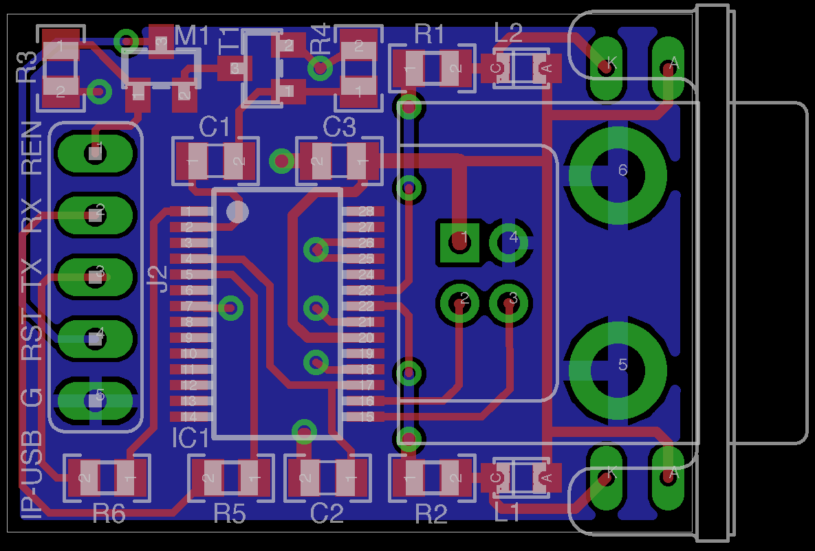
I have made a complete design ( USING EAGLE CAD ) for a small PCB with the circuit mentioned from my last post.
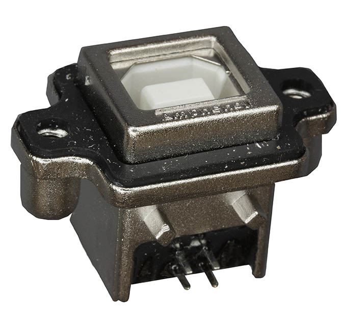
I plan to use the ( MUSBD111-XX) AMPHENOL HARSH ENVIRONMENT USB TYPE B Connector and dust cover. ( images attached)
The idea of this design is to add to an existing prop powered device, a USB port via a IP67 panel connection.
The circuit will allow normal USB comms , but if the user needs to upload new firmware to a prop device then the RESET ENABLE Line needs to be pulled hi ( via your own spin function) and then firmware can be loaded via SPIN or other similar software. I am hoping this will work !
I have added a through-hole LED mounting option for the TX & RX LEDS to poke through the panel as well.
Any comments welcome.
regards
Dave M
Post Edited (DavidM) : 4/24/2009 9:09:13 AM GMT


Comments
I am not sure what you mean by "COMPATIBLE" with the current prop-plug.
This design is meant to be used in a FINISHED DESIGN where the user would need normal USB functionality ( but without all the unnecessary resetting).
BUT on the RARE occasion the user/operator needs to update the prop firmware, then the user would initiate a "UPDATE FIRMWARE" routine from the existing PROP DEVICE.
While you are developing on your prop device you would just need to use the parallax prop-plug.
I guess i could add a small jumper to "DISABLE THE ENABLING??" if you wish to use the industrial prop-plug instead of the standard one. This could also be made into a switch as well.
regards
Dave M
So if one downloads a Spin prog. that never touches RESET ENABLE one can not download any more.
Is that really so ?
▔▔▔▔▔▔▔▔▔▔▔▔▔▔▔▔▔▔▔▔▔▔▔▔
For me, the past is not over yet.
yes that's how its supposed to work.
if you want to enable firmware updating , then you need in your application a routine to ENABLE the device. ( a few lines of code )
Then you can update the firmware via normal means. ( But note I have not tested this circuit yet, i am posting it here to get feedback)
regards
Dave M
You need to test your circuit first to make sure you can get a clean reset. I'm not sure if this is a problem, but there's a chance that as soon as /RST is pulled low, the Prop will tristate all its pins, which would disable the reset immediately, causing a runty pulse. This could result in an incomplete reset of the chip. The Propeller datasheet doesn't state how long the reset pulse has to be; so, unless someone in the know can chime in here, experimentation may be your only recourse.
-Phil
I have set up the LEDS in parallel , BUT ONLY ONE should be placed, either INTERNAL or the EXTERNAL led. ( or even none of them )
thanks
Dave M
I will add a 2 pin header for an optional switch, so that the enabling function can be controlled MANUALLY.
thanks
Dave M
You could be right!
The other option is to use a ANALOG SWITCH maybe?
I know I will need to test.
regards
Dave M
I will do this a different way. By default the device will behave like the standard propplug.
I will use an ANALOG SWITCH instead of the mosfet.
The analog switch I have chosen is the Texas-Instruments-SN74LVC1G66DBVR
This will be powered by a 3.3 v supply from the header.
The first 4 pins of the header J2 are arranged the same as the current propplug.
By default the analog switch will be pulled hi ( via the 10K resistor R3) which will allow the USB DEVICE to behave just like the standard PROPPLUG.
By pulling the Enable line Low, via SPIN code ( which can be part of your start up routine) , you can then disable the reset line so that plugging and unplugging the UDB connector will not reset the PROPELLER DEVICE.
I have updated the Schematic and the PCB Layout.
Any comments welcome.
thanks
Dave M
▔▔▔▔▔▔▔▔▔▔▔▔▔▔▔▔▔▔▔▔▔▔▔▔
Need to make your prop design easier or secure? Get a PropMod has crystal, eeprom, and programing header in a 40 pin dip 0.7" pitch module with uSD reader, and RTC options.
I swapped pins 5 & 6.
regards
Dave M
▔▔▔▔▔▔▔▔▔▔▔▔▔▔▔▔▔▔▔▔▔▔▔▔
Need to make your prop design easier or secure? Get a PropMod has crystal, eeprom, and programing header in a 40 pin dip 0.7" pitch module with uSD reader, and RTC options.
I am getting a local PCB manufacturer to make some of these, along with my IP-RS485 boards as well. They will be HAND SOLDERING some of each so I can test them as well as remake some more with any mods.
I will be incorporating these circuits into a larger board/project I am working on as well.
if this board works, do you think it possible to sell them?
regards
Dave M
▔▔▔▔▔▔▔▔▔▔▔▔▔▔▔▔▔▔▔▔▔▔▔▔
Need to make your prop design easier or secure? Get a PropMod has crystal, eeprom, and programing header in a 40 pin dip 0.7" pitch module with uSD reader, and RTC options.
Yes i guess i could sell these, at least to cover costs for my development,
I need to source other kinds of USB Connectors, My main aim is IP67/IP68 type for industrial /outdoor use. each different conector will require a different PCB Design. I am in the process of getting samples.
regards
Dave M
I have chosen a different connector, the BULGIN PX0447 as it is smaller than the other one.
Some Questions
Q1) According to the FTDI spec sheet ( page 22) for this Chip, they suggest to use a small ferrite bead ( MI0805K400R-10) , is this necessary?
Q2) are the resistors to the TX & RX pins of the IC required and/or are they the right value?
Q3) Will the ANALOG Switch circuit work?
regards
Dave M
Leon
▔▔▔▔▔▔▔▔▔▔▔▔▔▔▔▔▔▔▔▔▔▔▔▔
Amateur radio callsign: G1HSM
Suzuki SV1000S motorcycle
+3v3, gnd, then 4 i/os (which I am using the prop plug standard), so the propplug is the centre 4 pins of the 6 total.
I am designing using this pinout. If you use it, make sure you get the correct orientation to the pcb edge. Avnet also have FPGA boards with this pinout.
▔▔▔▔▔▔▔▔▔▔▔▔▔▔▔▔▔▔▔▔▔▔▔▔
Links to other interesting threads:
· Home of the MultiBladeProps: TriBladeProp, SixBladeProp, website (Multiple propeller pcbs)
· Single Board Computer:·3 Propeller ICs·and a·TriBladeProp board (ZiCog Z80 Emulator)
· Prop Tools under Development or Completed (Index)
· Emulators: Micros eg Altair, and Terminals eg VT100 (Index)
· Search the Propeller forums (via Google)
My cruising website is: ·www.bluemagic.biz·· MultiBladeProp is: www.bluemagic.biz/cluso.htm
i have room for the ferrite so I will update the board.
Thanks
Dave M
I will have a look at the pin arrangement you suggested
Thanks
Dave M