

Need Help Controlling a Turbo with Basic Stamp
 Torqued
Posts: 31
Torqued
Posts: 31
I purchased an· OEM Basic Stamp 2 back in July of 2000.· Really liked the concept and wanted to learn more.· Picked up several of the tutorial packages to get familiar with it and learn more about electronics.· I was impressed·by the capabilities and knew this was a device in seach of a project.
Fast forward 9 years.· Became interested in turbochargers and picked up a Garrett variable nozzle turbine (VNT)·turbo.· VNT turbos have vanes that swivel in the turbine to allow the turbo to spool faster at low rpms.· At higher·rpms, the vanes open up to allow the engine to breathe better.· The advantage of VNT technology is a broader torque curve than provided by a traditional turbo.
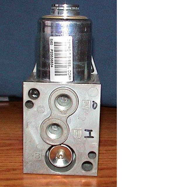
The turbo came from·a Detroit Diesel·engine.· DD controls the postion of the vanes by varying the pressure of compressed air fed to an actuator.· The engine control module (ECM)·sends PWM signals to a variable pressure output device (VPOD).· The VPOD takes in 90-120 psi air and outputs 0-75 psi depending on the PWM signal sent from the ECM.
I'm attempting to control the VPOD with my Basic Stamp.· I'm really weak when it comes to·the·electrical engineering aspects of this project. I would like to·get things set up properly without burning·out my·Stamp, my VPOD, or both.· Anybody willing to lend me a hand with this project?· I could sure use someone knowledgeable·in electronics (and Basic Stamp programming for that matter).
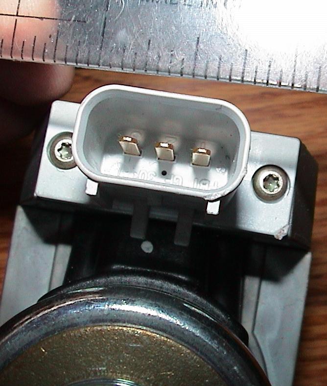
The VPOD has·a·3 wire plug.·The middle pin is for PWM (full open at 7% PWM and full close at 90% PWM).· One wire for +12V, other for ground.· Looking at different Detroit Diesel documentation, there seems to be a 12 and 24v version of the VPOD and·positive and negative·are swapped depending on which·voltage·you're running.· Mine is 12v.· Still trying to figure it out which wire goes where, if it matters.
Testing gameplan:· Supply 100psi to the VPOD from my compressor, put a gauge on the output, vary PWM using the Basic Stamp and observe pressure changes on the gauge.
Any takers?
Post Edited (Torqued) : 4/7/2009 7:18:39 PM GMT
Fast forward 9 years.· Became interested in turbochargers and picked up a Garrett variable nozzle turbine (VNT)·turbo.· VNT turbos have vanes that swivel in the turbine to allow the turbo to spool faster at low rpms.· At higher·rpms, the vanes open up to allow the engine to breathe better.· The advantage of VNT technology is a broader torque curve than provided by a traditional turbo.
The turbo came from·a Detroit Diesel·engine.· DD controls the postion of the vanes by varying the pressure of compressed air fed to an actuator.· The engine control module (ECM)·sends PWM signals to a variable pressure output device (VPOD).· The VPOD takes in 90-120 psi air and outputs 0-75 psi depending on the PWM signal sent from the ECM.
I'm attempting to control the VPOD with my Basic Stamp.· I'm really weak when it comes to·the·electrical engineering aspects of this project. I would like to·get things set up properly without burning·out my·Stamp, my VPOD, or both.· Anybody willing to lend me a hand with this project?· I could sure use someone knowledgeable·in electronics (and Basic Stamp programming for that matter).
The VPOD has·a·3 wire plug.·The middle pin is for PWM (full open at 7% PWM and full close at 90% PWM).· One wire for +12V, other for ground.· Looking at different Detroit Diesel documentation, there seems to be a 12 and 24v version of the VPOD and·positive and negative·are swapped depending on which·voltage·you're running.· Mine is 12v.· Still trying to figure it out which wire goes where, if it matters.
Testing gameplan:· Supply 100psi to the VPOD from my compressor, put a gauge on the output, vary PWM using the Basic Stamp and observe pressure changes on the gauge.
Any takers?
Post Edited (Torqued) : 4/7/2009 7:18:39 PM GMT
640 x 643 - 44K
668 x 788 - 75K
Comments
I've got a·wall wart·that supplies 12v to a cigarette lighter receptical, and a lighter plug with a fuse and two wires that I can power up my breadboard.· The VPOD needs 12v and the Stamp needs·9v or 5v.
What is the way to get the proper volts and amps, for the Stamp and the VPOD while sharing a common ground?· (Yes, I am an electronics newbie
Post Edited (Torqued) : 4/7/2009 8:00:34 PM GMT
▔▔▔▔▔▔▔▔▔▔▔▔▔▔▔▔▔▔▔▔▔▔▔▔
Basic Stamp,···· Propeller,·· · SX,·· FUN!
START:·
>Proccessing Data. . . .··
>Task Complete. . .·.
>Saving Data. . . .
>Entering SLEEP Mode. . . .
>Signing OFF
·
I will watch this post. Do you have an oscilscope and what are you planning on using the turbo on
Mike
·
So·the BS2 regulator can safely dump the heat from 12v down to 5v?· What about when the vehicle is running and the·voltage is higher than 12v due to the alternator?· Spikes?· Noise?
Looking for long term reliability.· If·the regulator is·up to the task as is, terrific.· But if this is a marginal solution, I would rather set it up properly up front.
I'll read up a bit on the optical isolators.· Thanks for the info and suggestions.
Post Edited (Torqued) : 4/7/2009 10:16:42 PM GMT
It's quite possible your turbo is not air actuated.· Some of the Holset VGT turbos (similar to VNT) use an electric stepper, while others use hydraulic pressure from the oiling system.· There's a variety of ways they operate, mine happens to be pneumatic.
I don't have a scope.· The·engine is a 502 BBC.· Came from GMPP with a·forged bottom end·(crank, rods, and pistons).· Suitable for moderate levels of boost.· Ring end gaps might be a little tight though.· The turbo can deliver enough air for 700-900 horsepower.· I'll be starting out much lower than that.
The battery idea was only for prototype work. In order to make it run off the car Battery, you will have to build a 12v Regulator. if you google it, you should be able to come up with a good circuit. I'll help you as much as i can.
▔▔▔▔▔▔▔▔▔▔▔▔▔▔▔▔▔▔▔▔▔▔▔▔
Basic Stamp,···· Propeller,·· · SX,·· FUN!
START:·
>Proccessing Data. . . .··
>Task Complete. . .·.
>Saving Data. . . .
>Entering SLEEP Mode. . . .
>Signing OFF
·
I had read up a bit on electronics last summer when I was contemplating this project.· Unfortunately, without applying it, most of the knowledge seems to have dribbled out of my head.·
▔▔▔▔▔▔▔▔▔▔▔▔▔▔▔▔▔▔▔▔▔▔▔▔
Basic Stamp,···· Propeller,·· · SX,·· FUN!
START:·
>Proccessing Data. . . .··
>Task Complete. . .·.
>Saving Data. . . .
>Entering SLEEP Mode. . . .
>Signing OFF
·
I wonder if my OEM Basic Stamp 2 from July of 2000 has the same regulator.
From the packing slip: 27210 Summer Stamp Pack (Assembled)
On the stamp: OEM BASIC Stamp 2 Rev A
I think the regulator has a piece of metal protruding up with a hole in it: EM02AJ LM294OCT -5.0 P+
▔▔▔▔▔▔▔▔▔▔▔▔▔▔▔▔▔▔▔▔▔▔▔▔
Basic Stamp,···· Propeller,·· · SX,·· FUN!
START:·
>Proccessing Data. . . .··
>Task Complete. . .·.
>Saving Data. . . .
>Entering SLEEP Mode. . . .
>Signing OFF
·
▔▔▔▔▔▔▔▔▔▔▔▔▔▔▔▔▔▔▔▔▔▔▔▔
Basic Stamp,···· Propeller,·· · SX,·· FUN!
START:·
>Proccessing Data. . . .··
>Task Complete. . .·.
>Saving Data. . . .
>Entering SLEEP Mode. . . .
>Signing OFF
·
http://www.parallax.com/StoreSearchResults/tabid/768/List/0/SortField/4/ProductID/67/Default.aspx?txtSearch=PWM+PAL
Not sure I understand when you need to·use one of these.· Is it so you can free up the processor on the Stamp to do other things like check sensor input while continuing to output a steady PWM until you need to change it?
Post Edited (Torqued) : 4/9/2009 5:06:14 PM GMT
Synatax for BS2 PWM is:
PWM pin, duty, cycles
Convert a digital value to analog output via pulse-width modulation.
-Pin is a variable/constant (0-15) This pin will be placed into output mode during pulse generation then switched to input mode when the instruction finishes.
-Duty is a variable/constant (0-255) that specifies the analog output level (0-5v).
-Cycles is a variable/constant (0-65535) specifying an approximate number of milliseconds of PWM output.
Pin: Easy enough.
Duty:· Analog output level (0-5v).· Found a scrap of information from a Detroit Diesel troubleshooting manual that might be helpful.· Apparently, the PWM signal from the·Engine Control Unit (ECU) sent to the VPOD on the middle pin·can be·as much as 12v (or more accurately, as much as 13.8v).··To troubleshoot,·the doc says to·connect a VOM (Volt/Ohm Meter?) across the PWM cavity in the plug to the ground cavity in the plug.· Using some other test equipment, get the·ECU to send a 50% duty cycle PWM.· The doc says you should see a voltage·of 6.8v, plus or minus 1 volt.· They show the calc (13.8v * 0.5 = 6.8v).· The Stamp puts·out a PWM signal of 0-5v.· So I'll need to do something to get the voltage into the range the VPOD is expecting.
ProcessingData recommended using an optical isolator between the Stamp and VPOD when sending the PWM signal to protect the Stamp.
Another question is how much current should be allowed to·flow through the PWM line?· Since I'm weak in electronics, I don't know how to think·this through.· Will the VPOD only take·the current·it needs and as long as I have at least enough current·available?· Or, do I need to limit the current·entering the VPOD·so it doesn't get damaged?· If I need to limit, how do I figure this out, or what is a safe approach to discovering what's required?
Cycles: How do I·determine the frequency the VPOD is expecting/requires?· Since I don't have access to a real Detroit Diesel 14 liter Series 60, the ECU, or the plug that feeds the VPOD, what is the·way to figure this out?· Where does the danger lie and what is the safe way of figuring this out?
Circuit Design: OK, we need optical isolation, and we need to amplify a 0-5v PWM signal to a 0-12v PWM signal, and we may or may not need to limit current flow entering the VPOD on the PWM line.· What does·the circuit that accomplishes these requirements look like?
Post Edited (Torqued) : 4/9/2009 5:08:12 PM GMT
Depending on the Opto type, you may need to add a 220-1k ohm resistor on the BS2 line.
▔▔▔▔▔▔▔▔▔▔▔▔▔▔▔▔▔▔▔▔▔▔▔▔
Basic Stamp,···· Propeller,·· · SX,·· FUN!
START:·
>Proccessing Data. . . .··
>Task Complete. . .·.
>Saving Data. . . .
>Entering SLEEP Mode. . . .
>Signing OFF
...So the optical isolator will not only protect my Stamp, but also bring my PWM up from 5v to 12v.· Great!· Seems almost too good to be true, but makes sense.· Many thanks!·
Do you have a part number·for the isolator you would recommend?
You mention a 10K Pot on the PWM line leading to the VPOD...is this to adjust the resistance/current flow to the VPOD?··Is·this to·"ease into" the testing of the·VPOD·by starting·out with a lot of resistance and gradually reducing it until the VPOD starts working?
Again, I apologize for my ignorance and really appreciate the help you're providing.
Post Edited (Torqued) : 4/9/2009 10:00:20 PM GMT
▔▔▔▔▔▔▔▔▔▔▔▔▔▔▔▔▔▔▔▔▔▔▔▔
Basic Stamp,···· Propeller,·· · SX,·· FUN!
START:·
>Proccessing Data. . . .··
>Task Complete. . .·.
>Saving Data. . . .
>Entering SLEEP Mode. . . .
>Signing OFF
Post Edited (ProcessingData...) : 4/10/2009 8:43:50 PM GMT
▔▔▔▔▔▔▔▔▔▔▔▔▔▔▔▔▔▔▔▔▔▔▔▔
Basic Stamp,···· Propeller,·· · SX,·· FUN!
START:·
>Proccessing Data. . . .··
>Task Complete. . .·.
>Saving Data. . . .
>Entering SLEEP Mode. . . .
>Signing OFF
Asked Parallax Support to makes some recomendations for an optocoupler to use with my BS2.· They wouldn't do it.
I'm looking at data sheets.· With my limited skills, I think I just need to try one and see if I can get it to work.· Not really the way I would like to go about it, but it's not like I'm going to go get a degree in EE to build one circuit.
I do wish I·knew more though...·
▔▔▔▔▔▔▔▔▔▔▔▔▔▔▔▔▔▔▔▔▔▔▔▔
Basic Stamp,···· Propeller,·· · SX,·· FUN!
START:·
>Proccessing Data. . . .··
>Task Complete. . .·.
>Saving Data. . . .
>Entering SLEEP Mode. . . .
>Signing OFF
·
▔▔▔▔▔▔▔▔▔▔▔▔▔▔▔▔▔▔▔▔▔▔▔▔
Basic Stamp,···· Propeller,·· · SX,·· FUN!
START:·
>Proccessing Data. . . .··
>Task Complete. . .·.
>Saving Data. . . .
>Entering SLEEP Mode. . . .
>Signing OFF
·
First , The PWM command from the BS2 does not work like this, it will not generate the signal that you are expecting. read that on the manual, this command generates an analog voltage on a pin, this is not what you need !
The 2940 -5.0 is perfect capable of holding the stamp in the voltage range that you described, even with peaks of 24v witch if your car is giving that, change your voltage regulator because this is not soposed to happen.
I would suggest some tests before star buying stuff ... Plug the 12V of your turbo regulator in a 12V supply, plug the ground to the ground and with an AMPmeter (I don´t know how to write that, I´m Brasilian, but is an AMPERE meter ) is series with the same 12V supply line plug it to the PWM control line of the turbo regulator, just to see how many amps we are talking about here, because by been an signal line this should be very small current.
If it really is that small current you will be able of making all your control with an Transistor (2n2904 or 2n2222) easely. and with PULSOUT command. (by small I meant up to 500mA witch is quite high)
Now, one question, do you have a controller for this unit ? or in the specs of it, it says the refresh rate of the PWM input? that should be given as a time of a frequency.
I concern about this because if you have a unit you can READ the PWM signal direct from it and make the BS2 generate one that´s equal. otherwise we have to go by the specs.
hope to help.
Amaral
The LM2940 - you're right, I could probably use it as is, others have.· Putting in a wider range regulator in front of the LM2940 is probably overkill, but seems like a cheap insurance policy for·$0.94.
The PWM command from the BS2 does not work like this, it will not generate the signal that you are expecting. read that on the manual, this command generates an analog voltage on a pin, this is not what you need !
You mentioned the Pulseout command as an alternative.· You may be right.· The problem is I don't have any documentation for the electronics of the VPOD.· It's something Detroit Deisel sells as part of a system, not as a standalone component that they issue a spec sheet for.· I have a couple of basic level·overview documents and methods·to troubleshoot the system, written for a Detroit Diesel service technician.
You mentioned If I had access to a controller I could use it to determine the proper signal to send it.· I've thought the same thing, unfortunately, I don't have access to one.· So what I'm doing here is trying to reverse engineer what this VPOD needs to see to operate, with limited information,·and I'm not an engineer.· This is one of the reasons I'm here looking for help.
Here's a link to·a version of the·tech guide.· There is a·good diagram on page·18 of the·PDF that·provides an overview of how the system works.· I've got a version on CD I was trying to post earlier, but the file is too large.
http://diesel.btc.ctc.edu/Engines/Detroit%20Diesel/EGR%20s60techguide.pdf
I need to re-read this·online version·for additional details because it is slightly different from my CD version.
In terms of trying to determine the proper signal to send,·can you think of·an approach to figuring this out that would not risk damaging the circuitry in the VPOD?· I will try your ammeter suggestion.
Post Edited (Torqued) : 4/11/2009 2:58:46 PM GMT
Page 120 - shows the wiring·diagram for a 12v VPOD.
Pin· Function
1··· +12v
2··· PWM
3··· Ground
The turbo also has a speed sensor to tell the computer how fast it is spinning so you don't spin it over 100k by tightening the vanes too much at the wrong time.· The diagram shows the pins on the tach plug.
Pin···Function
1···· Turbo Speed
2···· Sensor Return (452 looks to be a common ground for all the sensors)
3···· Plugged (not used)
From page 64 - Checking VPOD Wiring
5. Using a DDR/DDDL, activate the PWM #2 (EGR Valve) and PWM #4 (VNT), and ensure:
[noparse][[/noparse]a] Activating 11 % duty cycle: VDC = 90% of the VPOD supply voltage ± 1 volt (e.g. voltage to VPOD = 13.8V * 0.9 = 12.42V; therefore 11.42V to 13.42V at PWM is okay.)
[noparse][[/noparse]b] Activating 90 % duty cycle: VDC = 10% of the VPOD supply voltage ± 1 volt. (e.g. voltage to VPOD = 13.8V * 0.1 = 1.38V, therefore 0.38V to 2.38V at PWM is okay.
From page 96 - Comparing the new computer to the old.
PWM outputs: 6 vs 4 (Lo side)
Hmmm...lo side PWM outputs.· 11% duty cycle = 90% of the VPOD supply voltage and 90% duty cycle =10% of the VPOD supply voltage.· Hmmm...
So we've got 3 wires feed the VPOD.· 1: +12v·· 2: PWM·· 3: Ground.
Based on these clues, I'm guessing the PWM circuit is·normally high, and they are driving it low in example [noparse][[/noparse]b] 90% of the time to achieve a 10% of the supply voltage?·
Anyone interpret this differently?
Say you want to output a 5v high for 10 milliseconds, (each number 1, 0, is high or low for that millisecond)
you would output it with a high command, and it would look like this: (1111111111)
Then, you want to output a 2.5v signal for 10ms. You write:
PWM 0, 127, 10
It outputs this: (1010101010)
It gives 2.5v in theory because the pin is high for only half the time. So, an optoisolater should work.
▔▔▔▔▔▔▔▔▔▔▔▔▔▔▔▔▔▔▔▔▔▔▔▔
Basic Stamp,···· Propeller,·· · SX,·· FUN!
START:·
>Proccessing Data. . . .··
>Task Complete. . .·.
>Saving Data. . . .
>Entering SLEEP Mode. . . .
>Signing OFF
·
Amaral