

Help request for a BS1 project
 luisr320
Posts: 3
luisr320
Posts: 3
Hello all.
I'm building a project to use on a aircraft simulator at a Flying School used for pilot training.
The original project started as a device which would the following:
When the pilot pushes the "Go-Around" push-button that is located in the throttle he would activate the "Heading" (HDG) and "Indicated Airspeed" (IAS) modes of the Auto-Pilot (A/P) instead of the original "Go-Around" mode. It would do this using relays to shunt both push-buttons on the A/P panel, one at a time and in a sequence of about 1 second for each action.
I started to build the circuit with 555 on monostable configuration but a new problem showed up: if the HDG mode or the IAS mode were already active, the project would turn those modes OFF instead of ON, which I didn't wanted to happened. This is because each push on those buttons cycle trough ON/OFF for each mode.
So this is where the Basis Stamp came in. From a project nightmare it turned in a fairly simple thing to do. One input pin of the BS1 would detect that the G/A push-button was pressed and would do the following sequence:
1- Check if IAS mode already active.
2- If IAS mode is already active goto next step and if not, make a ouput pin drive a relay trough a transistor, wait 1 second and goto next step
3- Check if HDG mode already active.
4- If HDG mode is already active loop to the beginning and do nothing and if not, make a ouput pin drive a relay trough a transistor, wait 1 second and goto next step
5- Loop to the beginning and check for G/A Push-button
A small routine waits for the pilot to release the G/A Push-button before restarting the loop.
The problem that I needed to solve was this: How do I check that the HDG or the IAS mode were already active or not.
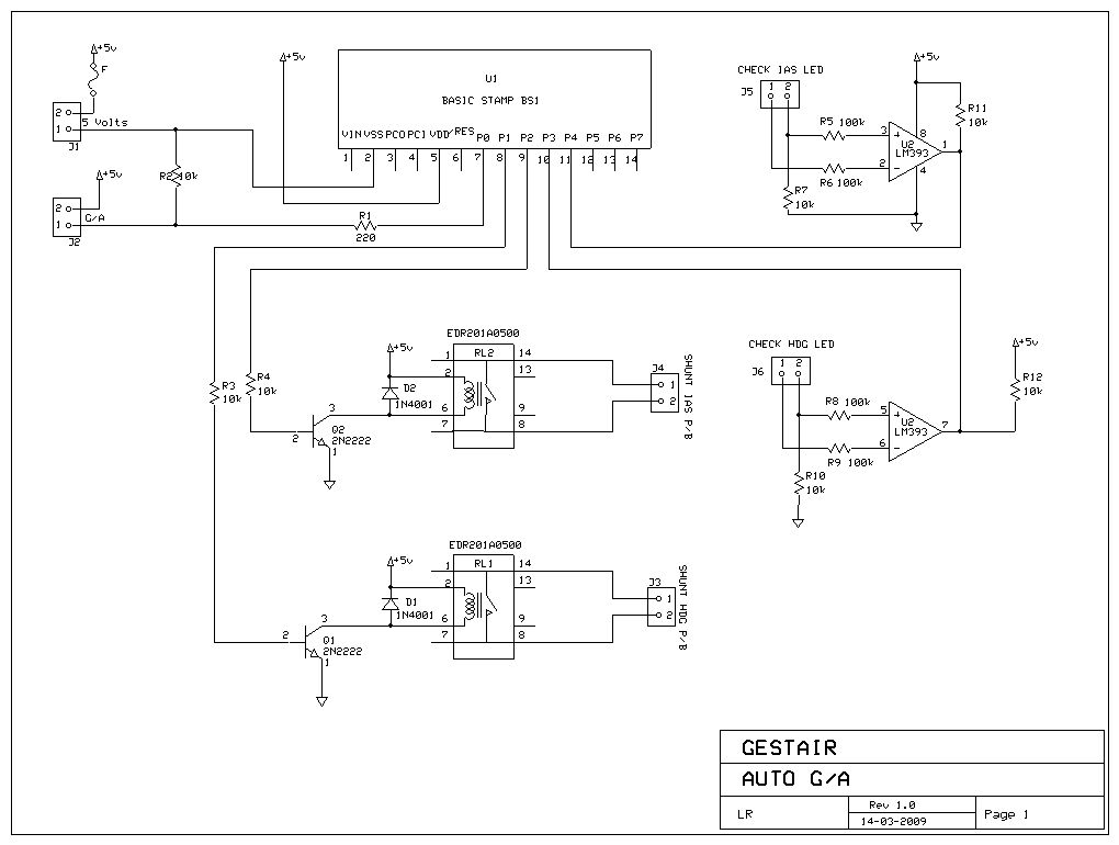
Well, when these modes are active, an LED lights up on the AP panel for each one of them. So it would be a matter of making the BS1 check if those LEDs were lit or not.
Through another forum I got some very useful help and ended up using a comparator (a LM393) connected to both sides of the LED to compere the voltage drop. It worked perfectly.
My question to you is: how would you go about checking if the LED's are lit or not? The LEDs are driven from a 12 volts power supply trough a 3.3k resistor and are controlled by a CAN Bus system. Is there a KISS way to do this or using the 393 is a good solution?
The schematics of the circuit is attached.
Thank you

Post Edited (luisr320) : 3/19/2009 1:26:42 AM GMT
I'm building a project to use on a aircraft simulator at a Flying School used for pilot training.
The original project started as a device which would the following:
When the pilot pushes the "Go-Around" push-button that is located in the throttle he would activate the "Heading" (HDG) and "Indicated Airspeed" (IAS) modes of the Auto-Pilot (A/P) instead of the original "Go-Around" mode. It would do this using relays to shunt both push-buttons on the A/P panel, one at a time and in a sequence of about 1 second for each action.
I started to build the circuit with 555 on monostable configuration but a new problem showed up: if the HDG mode or the IAS mode were already active, the project would turn those modes OFF instead of ON, which I didn't wanted to happened. This is because each push on those buttons cycle trough ON/OFF for each mode.
So this is where the Basis Stamp came in. From a project nightmare it turned in a fairly simple thing to do. One input pin of the BS1 would detect that the G/A push-button was pressed and would do the following sequence:
1- Check if IAS mode already active.
2- If IAS mode is already active goto next step and if not, make a ouput pin drive a relay trough a transistor, wait 1 second and goto next step
3- Check if HDG mode already active.
4- If HDG mode is already active loop to the beginning and do nothing and if not, make a ouput pin drive a relay trough a transistor, wait 1 second and goto next step
5- Loop to the beginning and check for G/A Push-button
A small routine waits for the pilot to release the G/A Push-button before restarting the loop.
The problem that I needed to solve was this: How do I check that the HDG or the IAS mode were already active or not.
Well, when these modes are active, an LED lights up on the AP panel for each one of them. So it would be a matter of making the BS1 check if those LEDs were lit or not.
Through another forum I got some very useful help and ended up using a comparator (a LM393) connected to both sides of the LED to compere the voltage drop. It worked perfectly.
My question to you is: how would you go about checking if the LED's are lit or not? The LEDs are driven from a 12 volts power supply trough a 3.3k resistor and are controlled by a CAN Bus system. Is there a KISS way to do this or using the 393 is a good solution?
The schematics of the circuit is attached.
Thank you
Post Edited (luisr320) : 3/19/2009 1:26:42 AM GMT
1020 x 770 - 75K
Comments
BTW, 3.3K sounds too high for a series LED resistor. It would only let ~3 mA flow through your LED. Check that.
▔▔▔▔▔▔▔▔▔▔▔▔▔▔▔▔▔▔▔▔▔▔▔▔
·"If you build it, they will come."
The 393 works perfectly on the breadboard. I guess I'm just trying to get the KISS method.
The thing is that the LED is part of a certified circuit which I don't want to change.
The grounds are in fact common. The 3.3k resistance is part of a pack of 15 resistors for all the LEDs that are part of the A/P mode panel.
I measured the voltage between the anode and the ground and got 12 volts when the LED is OFF. But when the LED is ON I get about 9.8V between ground the anode.
The ground part of the LED goes inside the CAN control box.
What does it mean to have 12V on the LED with it OFF and 9.8 with it ON?
Here is the schematics of the simulator.
Consider the LED's that are there as those to be monitored.
Thank you.
▔▔▔▔▔▔▔▔▔▔▔▔▔▔▔▔▔▔▔▔▔▔▔▔
·"If you build it, they will come."