

Basic Stamp 1 Problem
 thanasis_leo
Posts: 23
thanasis_leo
Posts: 23
I have bought a Basic Stamp 1 Starter Kit.
1.I connected the Basic Stamp to the Motherboard that it came with.
2.I installed the Basic Stamp Editor to the computer
3.I connected the motherboard with serial port to the computer.
4.I connected the motherboard with a 9 Volt battery.
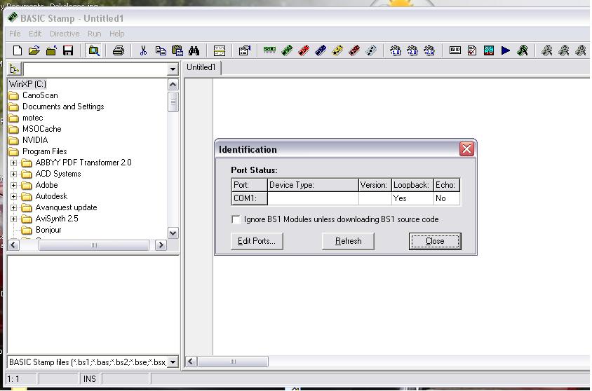
5.I selected Run->Identify
6.Deselected the "Ignore BS1 Modules unless download BS1 source code"
7.The port that it was selected it was the correct port.
And the result is that in Device Type there is nothing written, in loopback it says Yes and in Echo it says No.
I tried to connect only the BS1 module with it's serial adapter but I had the same results.
The same results I had when I tried it to another computer.
Do you know what's wrong?
I think the BS1 module is defective.
Post Edited (thanasis_leo) : 12/10/2008 5:23:03 PM GMT
1.I connected the Basic Stamp to the Motherboard that it came with.
2.I installed the Basic Stamp Editor to the computer
3.I connected the motherboard with serial port to the computer.
4.I connected the motherboard with a 9 Volt battery.
5.I selected Run->Identify
6.Deselected the "Ignore BS1 Modules unless download BS1 source code"
7.The port that it was selected it was the correct port.
And the result is that in Device Type there is nothing written, in loopback it says Yes and in Echo it says No.
I tried to connect only the BS1 module with it's serial adapter but I had the same results.
The same results I had when I tried it to another computer.
Do you know what's wrong?
I think the BS1 module is defective.
Post Edited (thanasis_leo) : 12/10/2008 5:23:03 PM GMT
844 x 558 - 64K
1024 x 768 - 116K
1024 x 768 - 114K
1024 x 768 - 106K
Comments
You might try another serial cable. "Echo" should be Yes if the serial connection to the serial adapter is intact.
▔▔▔▔▔▔▔▔▔▔▔▔▔▔▔▔▔▔▔▔▔▔▔▔
·"If you build it, they will come."
Post Edited (erco) : 12/10/2008 4:51:52 PM GMT
When I use it with the serial adapter and the customized cable ,here is what I get:
The two most common causes of "failure to find a Stamp" are:
1) Lack of power or inadequate power to the Stamp
2) Lack of correct serial connection to the Stamp.
....When you use a USB to serial adapter, you have to have the correct driver.
Shouldn't it have worked with the Development board's serial adapter ?
Post Edited (thanasis_leo) : 12/10/2008 5:49:22 PM GMT
The Development Board's BS1 Serial Adapter should work fine. I was commenting about the serial cable attached to it. Make sure that's correct.
Eliminate as many variables as you can: use a 9 volt battery, stock serial cable, direct connection to serial connector, and try to run a simple program.
▔▔▔▔▔▔▔▔▔▔▔▔▔▔▔▔▔▔▔▔▔▔▔▔
·"If you build it, they will come."
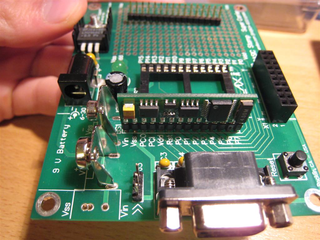
The starter kit came with a BS1 module , a BS Super Carrier, a serial cable and BS1 Serial adapter.
In my first post ,you can see that I am trying to connect the BS1 to the computer with the Super Carrier and the serial cable that it came with the package(is this an ordinary serial cable or it is a custom made for BS1 serial Adapter?)
I tryed to connected to another computer with a different cable but I had the same results.
After, I tried to connect the BS1 module with the Serial adapter and a Customized cable . The only result was Yes in Echo. Nothing else.
I tried to connect the BS1 module with the Serial adapter in the Super Carrier and the Serial cable that it came with and the result is No both on Loopback and Echo.
The DB9 connector that is part of the Super Carrier Board is not used for the BS1. It is for use with the BS2 series modules only. It's not connected to the BS1 socket.
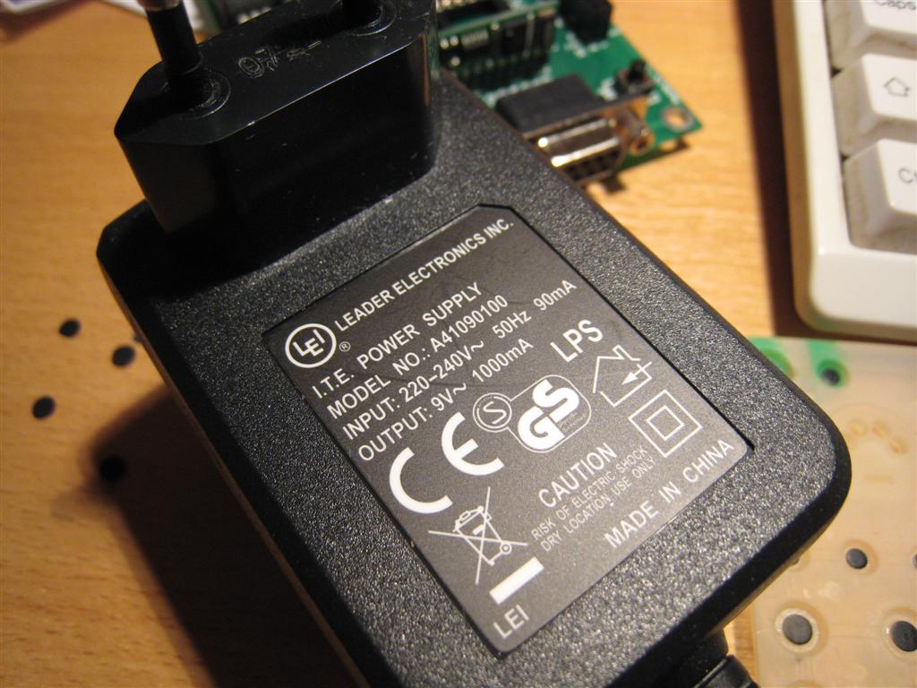
Unless there is a problem with the 9V AC adapter, I don't see any particular reason why your setup should not work.
I suggest you call or e-mail directly to Parallax's Technical Support department. They may have some other suggestions for you to try or may just replace your kit.
▔▔▔▔▔▔▔▔▔▔▔▔▔▔▔▔▔▔▔▔▔▔▔▔
·"If you build it, they will come."
I dont think you are right.
Because as you can see from the picture , th PCO,PCI and VDD are connected with the serial port.So the serial port is connected with the BS1 socket.
Ok, let's say that you are right. For which reason does the super carrier come with the BS1 module ?
Can anybody here please show me how to do the correct connection with the cables on the wire?
For example ," The No1 cable you should replace it with No2,The no3 cable you should replace it with No6 etc."
I will check tomorrow the custom cable to see if I have made any mistake.Now I have to go to sleep because here is GMT +2 .
[noparse][[/noparse] Schematic for Super Carrier Board ]
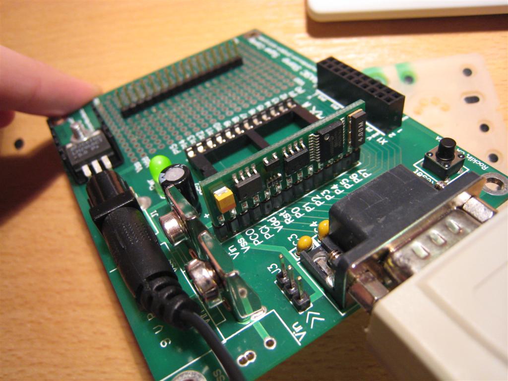
Two things I noticed on your pictures. I don't have a BS1, but I always have a Jumper on my VIN, Yours is J3. Could this be your problem. Also, your voltage should be DC regulated going in. You might put a fresh battery and see if this helps. I may be all wet, but I have a desire to help you.
It ain't·me, man --·a) that's Parallax's schematic [noparse][[/noparse]a section of it]·and b) thansis_leo is the one having the trouble.
▔▔▔▔▔▔▔▔▔▔▔▔▔▔▔▔▔▔▔▔▔▔▔▔
Chris Savage
Parallax Engineering
For example, The No1 cable you should replace it with No2,The no3 cable you should replace it with No6 etc."
Also, in his last post, T_L brought up the "serial port".
" The No1 cable you should replace it with No2,The no3 cable you should replace it with No6 etc."
This will really help me.
Here is my cable. Is it correct ?
To program a BS_1 with the serial adapter on the Super Carrier Board (as you are!)·your cable should be like the one I noted in my post with the schematic and which Mike Green called your attention.
Post Edit -- 1 Basic Stamp Programming Manual, Version 2.0c, "page 27"
Post Edited (PJ Allen) : 12/12/2008 12:31:21 AM GMT
Shouldn't I do this modification ?
In your schematic ,this is an ordinary serial cable, isn't it?
Does the cable In your pic IMG_4335 have a male on one end and a female connector on the other?
Yes, in the female port I have connected as you can see the BS1 Serial Adapter.
The male port I connect it to the PC Serial Port.
OOOOOOO
I dont know what to do....
It's 3 o' clock .I am going to bed.
See you tomorrow .
Post Edited (thanasis_leo) : 12/12/2008 1:18:54 AM GMT
This will help me a lot.