

XBee 2.5 Still Not Working with BS2
 kenwtn
Posts: 250
kenwtn
Posts: 250
Hi,
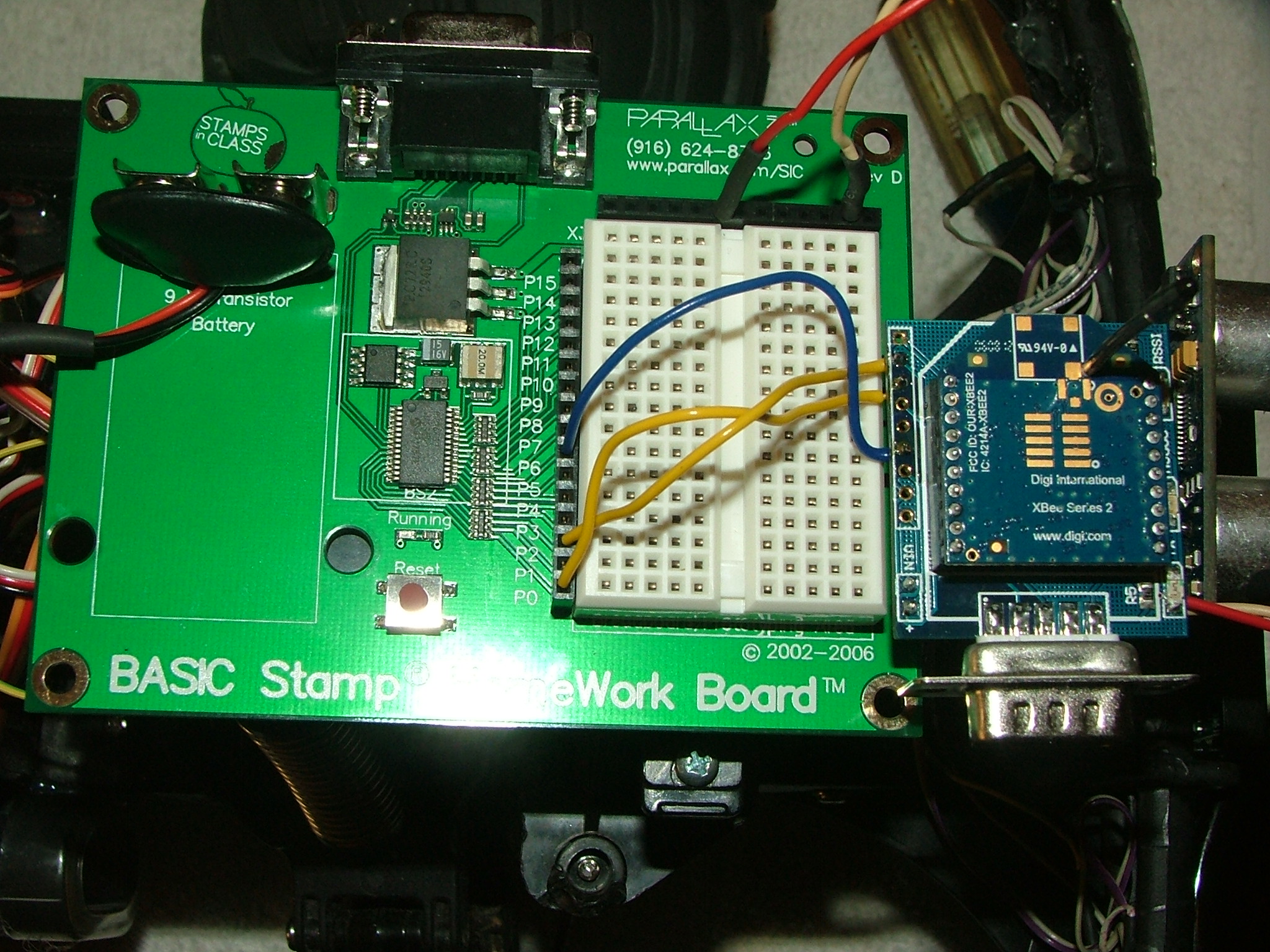
··· I have been working with Microcontroller where I bought the DTE Boards I am using but still I have not got this working. I have attached Picture of my connections and sample code I m using. I have both transmit side and receive side wired the same way. Any ideas would be a big help.
··· I have been working with Microcontroller where I bought the DTE Boards I am using but still I have not got this working. I have attached Picture of my connections and sample code I m using. I have both transmit side and receive side wired the same way. Any ideas would be a big help.

Comments
The xbee series 2 that you have and the xbee series 1 for which that code was written are different devices. Different hardware, different firmware, different network. Digi also has a forum where you can post questions, although it is not very active. Still, you can homeworrk through the posts there and glean useful insights.
In general, when you have a thread started that brings up an issue, you should post to that same thread so people can pick up on the issues.
▔▔▔▔▔▔▔▔▔▔▔▔▔▔▔▔▔▔▔▔▔▔▔▔
Tracy Allen
www.emesystems.com
It is a useful question, because there is confusion about the different flavors of xbee. Other people thinking about this need to be clued in. Digi in my opinion doesn't do a good job with the caveats. At the embedded systems conference a few weeks ago Digi/Maxstream was there and I bought the development kit (a great show deal) that included three xbee modules, a wall router and a connectPort X2 gateway (ethernet--programmable in Python). At the time I had no idea about the differences between series 1 and series 2 and thought I would have a lot of examples to go on from Martin's Selmaware projects. But of course these were series 2 devices and a period of frustration ensued, such as you are experiencing, before I dug and realized there were significant differences. The connectport gateway came pre-programmed as the coordinator, and the rest of the modules as routers. We had to reflash the firmware anyway, to get it up to version 1.x.4.1, and make one of the other modules the coordinator, because our target project (for air pollution monitoring) will not be able to use the connectPort.
▔▔▔▔▔▔▔▔▔▔▔▔▔▔▔▔▔▔▔▔▔▔▔▔
Tracy Allen
www.emesystems.com
Perhaps some more light (or not!) on the subject...
In all cases, "PRO" seems to designate the high-power version.
Series 2 is now series 2.5
Xbee Znet is older firmware than Xbee ZB.
Neither Znet nor ZB are compatible with Series 1, nor are they compatible with each other, but Znet can be "upgraded" to ZB and ZB can be "downgraded" to Znet. Series 1 cannot...
It appears the any 2 units are supposed work together hands-off out of the box IF they are the same series.
If any of the above appears to be incorrect, shout it out. I could easily have misread something...
Regards,
Terry (who has been threatening to buy several modules for a weather station, gate monitoring, etc.)
Post Edited (kenwtn) : 6/22/2008 8:07:46 PM GMT
Terry,
Agree with some statements, not others.
-- "Pro" is higher power in either series, 50 or 100 milliwatts vs 1 or 2 milliwatts, and about $10 more for Pro.
-- What was originally called "XBee series 2" is now called "XBee ZNet 2.5" and is optimized for mesh networking with multiple hops
-- The original XBee, which was for a while called "series 1" to distinguish it from "series 2" is now called "XBee 802.15.4" and is optimized for single point to multipoint networking.
. The original XBee is the one to have if you want to use the Selmaware code examples.
. The purpose of the two series are somewhat different, and I don't see anything about the earlier series being discontinued.
-- I don't know about anything called ZB independent of ZNet, in either hardware or firmware.
-- XBee ZNet 2.5 is a different hardware platform than the older XBee. Non-interoperable, so you can't turn a series 1 into a series 2 or vice versa with a firmware change.
-- The current firmware for XBee ZNet 2.5 is version 1.x.4.1, where x designates the mode, coordinator vs. router/endpoint, and interface, command vs API.
-- The current firmware for XBee 804.15.4 is 10C8. One firmware for all devices in the network.
-- There are thorough revision histories available on the Digi web site.
-- Hands on out of the box is relative. (A joke you'd think in frustration!) That was relatively more true for the original XBee (XBee 802.15.4), because the same firmware resides on all devices in the network, and roles were changed using commands. Of course, you do have to give it the correct commands to discover and set the network addressed, before any taling back and forth is possible. In series 2, one device in the network _has_ to be burned with the separate coordinator firmware. It works "out of the box" only if that has been done, and most of the devices come "out of the box" with the router/endPoint firmware, not coordinator firmware. But once that is done and a few fundamentals are understood, it is equally easy to get either type of network talking. (but I'm just beginning at this too.)
▔▔▔▔▔▔▔▔▔▔▔▔▔▔▔▔▔▔▔▔▔▔▔▔
Tracy Allen
www.emesystems.com
The problem is that you connected to the row of solder islets on the side of the board. I can't tell for sure, but, from the description and the appearance of the board, these look like they provide a direct connection to the xBee pins which are 3.3V logic. The DB-9 connector provides an RS232 connection with the protection of an RS232 to 3.3V logic converter/translator. The solder islets provide no protection and any voltage above 3.3V or less than zero applied to those islets will likely burn out the attached xBee pin circuitry.
The description of a serial connection using a Stamp with a 22K resistor that is in the PBasic manual, would probably have worked if you connected to the DB-9 (serial) connector on the DTE board. At least it wouldn't have damaged the xBee.
Post Edited (kenwtn) : 6/23/2008 3:46:48 PM GMT
What probably happened is that the Stamp was using +5V to signal to the xBee's RX and RTS inputs. This is greater than the xBee's 3.3V supply voltage. There are usually "protective" diodes from I/O pins to the supply lines (3.3V and ground). These are connected "backwards" so they don't normally conduct. If the input pin is connected to a source of negative voltage (below -0.6V) or a source higher than the supply voltage (above 3.9V), these diodes will conduct to the + supply bus on the chip or to the ground bus. If there's enough current available, the diodes or the connecting "wires" will eventually melt damaging the circuitry around them. Even if there's not enough current available to cause heating, the voltage "spike" can damage the chip if it's high enough or lasts for long enough.
Post Edited (Mike Green) : 6/23/2008 4:11:04 PM GMT
To test it, you could to hook the XBee module up to your computer's serial port via a crossover (null modem) cable, to the DB9 connector. Leave it powered from your homework board, but remove the other rx and tx and rts connections that you have to Stamp pins. Then run a terminal program such as hyperterminal. Type "+++" in quick succession to put the XBee in command mode. If it responds "OK", then it is not burnt out. Then you can try a couple of other XBee AT commands, such as "ATMY" CR, or "ATND",CR to see if the module is alive. Remember that commands have to be entered within 10 seconds of one another, or else the module automatically goes out of command mode back into transparent mode, and you will have to enter "+++" again to reenter command mode. Those commands/responses do not depend on having a network connection.
I highly recommend that you get a connection going from the XBee directly to your desktop PC, so that you can get a feel for the command set.
▔▔▔▔▔▔▔▔▔▔▔▔▔▔▔▔▔▔▔▔▔▔▔▔
Tracy Allen
www.emesystems.com
▔▔▔▔▔▔▔▔▔▔▔▔▔▔▔▔▔▔▔▔▔▔▔▔
Tracy Allen
www.emesystems.com
If I buy replacements I think I will want the SERIES 1
Don't throw your earlier XBees in the trash quite yet. One of the first rules of troubleshooting--the possibility that the test setup might be defective. If you had seen a positive "OK" response in the above test, that would show that the XBee was working. But seeing no response does _not_ prove that the XBee is toast. It might be that the cable is incorrect, or that something is wrong with the carrier board or the power supply, or that your PC or hyperterminal are not configured correctly. The better test would be to see that the test setup works with a device known to be good (as in a brand new XBee), and then use the same setup for a device that is questionable.
▔▔▔▔▔▔▔▔▔▔▔▔▔▔▔▔▔▔▔▔▔▔▔▔
Tracy Allen
www.emesystems.com
I understand "relative"! And I can see that, in order to work "out of the box", one device would have to be configured as a coordinator; but that was Maxstream's claim. I believe (don't recall for sure) that their eval kits do come that way...
You commented that you don't know anything about ZB being independent of Znet, in hardware or firmware. I found this is the ZB product manual:
quote: The XBee/XBee-PRO ZB firmware release can be installed on XBee modules. This firmware is
compatible with the ZigBee 2007 specification, while the ZNet 2.5 firmware is based on Ember's
proprietary "designed for ZigBee" mesh stack (EmberZNet 2.5). ZB and ZNet 2.5 firmware are
similar in nature, but not over-the-air compatible. Devices running ZNet 2.5 firmware cannot talk
to devices running the ZB firmware.
I am learning a lot from this thread! (which will be put to good use)
kenwth,
As Tracy says, don't throw them out yet! There is a list as long as your arm of things that could be causing problems, but aren't fatal...
Terry (Having been faced more than once with the bench tech's dilemma )
Then the serial number of the target has to be entered into the XBee that wants to send the message, using the ATDH, ATDL and ATWR commands.
I was concerned that there was a serious weak link in the network, if the coordinator goes kerplunk. The coordinator does provide advanced services, but I was relieved to find that there are workarounds and that it is possible to establish communication on a crude device to device level.
Terry, I see what you mean about the new XBee ZB firmware, that would seem to supercede the XBee ZNet 2.5 firmware, but runs on the XBee ZNet 2.5 (aka "series 2") hardware. It seems everything is in a constant state of transition; as of today, there are two incompatible versions of XBee hardware available from Digi/Maxstream, and three incompatible versions of firmware. Caveat Emptor.
Here is the link to the Digi page, and a link there will download a folder with documentation for XBee ZB and the firmware required to burn into coordinators, routers and end devices. (6 different firmware versions between those three device performance options and the two AT vs API interface options)
www.digi.com/support/kbase/kbaseresultdetl.jsp?id=3025.
▔▔▔▔▔▔▔▔▔▔▔▔▔▔▔▔▔▔▔▔▔▔▔▔
Tracy Allen
www.emesystems.com
' {$STAMP BS2pe}
' {$PBASIC 2.5}
' **************************************
' * Config_XBeeZNet25_SEROUT.bpe    *
' * Illustrates configuring the XBee   *
' * from the BASIC Stamp.              *
' * see caveats about channel selection *
' **************************************

' read the 64 bit serial number off the bottom of the target zigbee module
' and enter it here.  16 ascii hex characters:
' For example, my target module is 0013A200 405421A0.
destHi1    CON $0013     ' target Node high Address
destHi0    CON $A200
destLo1   CON $4054
destLo0    CON $21A0

Baud      CON 84     ' Baud rate, 9600, 8-N-1, non-inverted, on BS2.

RX        CON 16      ' Receive Pin
TX        CON 16      ' Transmit Pin

TICK    VAR BYTE


HIGH TX

DEBUG CLS, "Configuring XBee..."
PAUSE 2000                               ' Guard time for command sequence
SEROUT TX,Baud,[noparse][[/noparse]"+++"]                   ' Enter command mode
PAUSE 2000                               ' Guard time for command sequence
SEROUT TX,Baud,[noparse][[/noparse]"ATDH ", HEX4 destHi1,HEX4 destHi0,CR, ' Set destination node address
            "ATDL ", HEX4 destLo1,HEX4 destLo0,CR, ' Set destination node address
               "ATCN",CR]                ' Exit command mode

PAUSE 1000
DEBUG "Configuration Complete!",CR
DO                                       ' Send message forever at 1S intervals
  SEROUT TX,Baud,[noparse][[/noparse]"Hello Node! ",DEC TICK, CR]
  PAUSE 1000
  TICK=TICK+1
LOOP
One caveat is that the two devices have to be operating on the same channel. On series 1 the channel can be both read and set, but on series 2 it is read only. One role of the coordinator is to select the best channel and pass that value (read only) to all of the other XBees on its network. Nonetheless, my series 2 XBees all came up with a default to channel D, and were able to communicate with that default setting. The documentation implies that a series 2 XBee won't have any channel at all until the coordinator passes it one. But that does not seem to be true, but I wouldn't count on it.
▔▔▔▔▔▔▔▔▔▔▔▔▔▔▔▔▔▔▔▔▔▔▔▔
Tracy Allen
www.emesystems.com
Thanks so much for keeping me posted on what you have found. I also appreciate the sample code. GOOD JOB!
Ken
▔▔▔▔▔▔▔▔▔▔▔▔▔▔▔▔▔▔▔▔▔▔▔▔
Keep buying replacement parts and sooner or later you will get it RIGHT!
Tracy, Thanks for all of the words of wisdom.
This has saved me a lot of potential head-banging, and has caused me to do my homework ahead of time, instead of after (my usual mode)
Cheers,
Terry
However, as soon as I powered up an old series 2 module that had already been part of a network, on PAN id 0x234 and channel D, the new modules (after reset) immediately saw that and formed a network of 3 devices that could send data back and forth to one another. The association lights started blinking. The old device that seeded the network was _not_ programmed with the coordinator firmware. It was a router programmed with the same firmware as the new devices.
The channel number, once acquired, sticks with the device even after the network is shut down and even survives the ATRE (reset to default settings) command. The reset command does rest the PAN id back to its default value of 0x234 (The documentation says otherwise).
So, observation 1: You have to have a coordinator at some point in time to set up a network.
And observation 2: The coordinator is not absolutely necessary to the subsequent establishment or survival of the network, once channels have been selected.
I don't want to make it seem too problematic to get these going. It really is easy once a coordinator is in the loop. In fact, once it is preconfigured and the settings stored in it's eeprom, the XBee can be a totally transparent serial cable replacement. I'm just trying to dig into the workings and robustness factors.
▔▔▔▔▔▔▔▔▔▔▔▔▔▔▔▔▔▔▔▔▔▔▔▔
Tracy Allen
www.emesystems.com
First of all, I would like to thank all of you for all of the enlightening XBee information. It has made it a lot easier to be able to get attempt to get two XBee 2.5 modules to talk to one another. However, I still have some questions that you might be able to answer.
I bought two XBee 2MW Series 2.5 from Sparkfun and plan to use them with my·BS2p controlled robot.
Using X-CTU, I found both modules to be ZIGBEE router/end devices which means that I will have to program one of them to be a ZIGBEE coordinator to be able to form a network and communicate with each other, right?
Is, as terry_bear has said, ZIGBEE (ZB) firmware newer than ZNET 2.5? In other words, should I stick with ZB and not reprogram to ZNET 2.5?
Regards,
TCIII
▔▔▔▔▔▔▔▔▔▔▔▔▔▔▔▔▔▔▔▔▔▔▔▔
If you are going to send·a Robot·to save the world, you·better make sure it likes it the way it is!