

Unexpected solar panel output (what am I doing wrong?)
 Bean
Posts: 8,129
Bean
Posts: 8,129
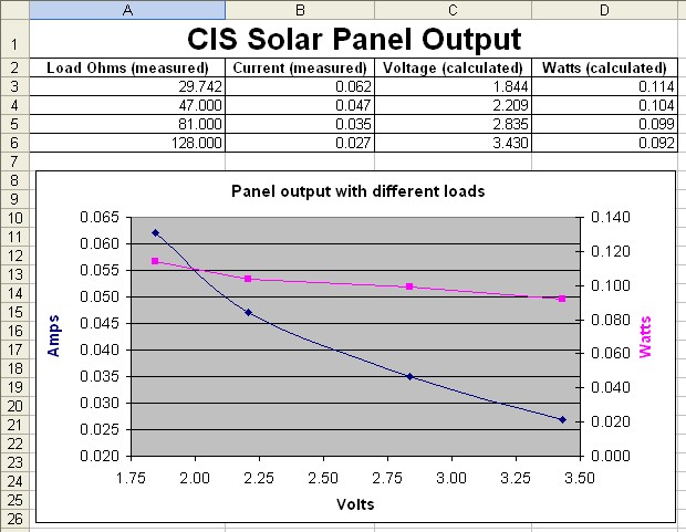
I purchased some solar panels from ebay.
I want to build my own MPPT·(maximum power point tracking) controller.
So I wanted to graph the I/V output from the panel.
I only had a 47 ohm and an 81 ohm resistor with me, so I measured the current of each, then with them in series and in parallel.
When I put the values into excel I didn't get anything like what a "normal" I/V graph looks like.
My solar cell seems to put out more watts at a lower voltage.
And all the info I can find says "Solar panel output is basically constant current", well mine is not even close.
I measured 4.73 volts open and 80.4mA short while conducting the test.
I'll try it again with a wider range of resistances when I get a chance.
Am I doing something wrong in the way I am trying to measure this thing ?
Right now I'm baffled ???
Bean.
·

▔▔▔▔▔▔▔▔▔▔▔▔▔▔▔▔▔▔▔▔▔▔▔▔
- - - - - - - - - - - - - - - - - - - - - - - - - - - - - - -
Did you know that 111,111,111 multiplied by 111,111,111 equals 12345678987654321 ?
www.iElectronicDesigns.com
Post Edited (Bean (Hitt Consulting)) : 4/14/2008 1:04:33 PM GMT
I want to build my own MPPT·(maximum power point tracking) controller.
So I wanted to graph the I/V output from the panel.
I only had a 47 ohm and an 81 ohm resistor with me, so I measured the current of each, then with them in series and in parallel.
When I put the values into excel I didn't get anything like what a "normal" I/V graph looks like.
My solar cell seems to put out more watts at a lower voltage.
And all the info I can find says "Solar panel output is basically constant current", well mine is not even close.
I measured 4.73 volts open and 80.4mA short while conducting the test.
I'll try it again with a wider range of resistances when I get a chance.
Am I doing something wrong in the way I am trying to measure this thing ?
Right now I'm baffled ???
Bean.
·
▔▔▔▔▔▔▔▔▔▔▔▔▔▔▔▔▔▔▔▔▔▔▔▔
- - - - - - - - - - - - - - - - - - - - - - - - - - - - - - -
Did you know that 111,111,111 multiplied by 111,111,111 equals 12345678987654321 ?
www.iElectronicDesigns.com
Post Edited (Bean (Hitt Consulting)) : 4/14/2008 1:04:33 PM GMT
620 x 481 - 82K
Comments
The panels are rated at 0.25 Watts. 4.5 volts open, 100mA short.
I measured 4.73 volts open and 80.4mA short while conducting the test.
I will measure the voltage too when I do the next test. I'll also test several different (same model) panels.
Bean.
▔▔▔▔▔▔▔▔▔▔▔▔▔▔▔▔▔▔▔▔▔▔▔▔
- - - - - - - - - - - - - - - - - - - - - - - - - - - - - - -
Did you know that 111,111,111 multiplied by 111,111,111 equals 12345678987654321 ?
www.iElectronicDesigns.com
·
If you didn't have any load on it, that may be the problem. The graph indicates the wattage given differing voltages, and ampere loads.
Regards,
Bruce Bates
▔▔▔▔▔▔▔▔▔▔▔▔▔▔▔▔▔▔▔▔▔▔▔▔
Involvement and committment can be best understood by looking at a plate of ham and eggs. The chicken was involved, but the pig was committed. ANON
The graph data points are different load resistances.
Bean.
▔▔▔▔▔▔▔▔▔▔▔▔▔▔▔▔▔▔▔▔▔▔▔▔
- - - - - - - - - - - - - - - - - - - - - - - - - - - - - - -
Did you know that 111,111,111 multiplied by 111,111,111 equals 12345678987654321 ?
www.iElectronicDesigns.com
·
I had always thought that a solar panel was a current source and that it was the voltage that was constant (for the better part).
Will look in to that I guess....
en.wikipedia.org/wiki/Photovoltaic_cells
This guy did a similar check....I don't have time to really cross-check, but at least it's a resource! [noparse];)[/noparse]
www.mtmscientific.com/solarpanel.html
▔▔▔▔▔▔▔▔▔▔▔▔▔▔▔▔▔▔▔▔▔▔▔▔
<FONT>Steve
What's the best thing to do in a lightning storm? "take a one iron out the bag and hold it straight up above your head, even God cant hit a one iron!"
Lee Travino after the second time being hit by lightning!
Post Edited (steve_b) : 4/14/2008 3:23:25 PM GMT
The results you got looks normal to me for a PV panel.
Most PV panels state a rated voltage and rated current figure.
At this rated values, the output wattage is maximum.
Yes, most PV panels are almost a current source.
For example, on my 52 watt panel, the rated current at 17v is 3.1amps but the short circuit current (zero volts) is only 3.6 amps.
A lot of people would have expected the short circuit current to be much higher, but that's the inherent charateristic of PV panels. (current source)
▔▔▔▔▔▔▔▔▔▔▔▔▔▔▔▔▔▔▔▔▔▔▔▔
www.fd.com.my
www.mercedes.com.my
You are measuring it right, but the maximum power point will occur at a lower voltage and lower resistance than you covered in your experiment. At higher current, it will come to the peak power and then will act more and more like a constant current source as it approaches a short circuit. The short circuit is of course, zero volts * 80.4 mA = zero watts. I usually plot watts as a function of current. The short circuit current is pretty much a linear function of input light in watts per unit area. The open circuit voltage is more complicated, near a logarithm of light intensity, with strong temperature dependence.
▔▔▔▔▔▔▔▔▔▔▔▔▔▔▔▔▔▔▔▔▔▔▔▔
Tracy Allen
www.emesystems.com
· Over my lunch time I used an R-Box and got these results.
· But I still don't know why the current changes so much on the left side ? All other graphs I see are very linear (with a slight drop) until they fall off at the higher voltage.
Bean.
▔▔▔▔▔▔▔▔▔▔▔▔▔▔▔▔▔▔▔▔▔▔▔▔
- - - - - - - - - - - - - - - - - - - - - - - - - - - - - - -
Did you know that 111,111,111 multiplied by 111,111,111 equals 12345678987654321 ?
www.iElectronicDesigns.com
Post Edited (Bean (Hitt Consulting)) : 4/14/2008 5:18:30 PM GMT
Here is a typical set of curves:
▔▔▔▔▔▔▔▔▔▔▔▔▔▔▔▔▔▔▔▔▔▔▔▔
Tracy Allen
www.emesystems.com
· Thanks I will check out a couple other panels (of the same model).
· These came from ebay, so defective cells are possible.
Bean.
▔▔▔▔▔▔▔▔▔▔▔▔▔▔▔▔▔▔▔▔▔▔▔▔
- - - - - - - - - - - - - - - - - - - - - - - - - - - - - - -
Did you know that 111,111,111 multiplied by 111,111,111 equals 12345678987654321 ?
www.iElectronicDesigns.com
·
Now you are talking !
Solar panels are useless without a MPPT.
I tried to get Martin (and others) interested in a basic stamp MPPT without luck.
I did build a crude MPPT using the Basic Stamp as part of my Renewable Studies.
I will post it and I hope you can improve on it and hopefully get some traction out there for stamp use in renewables.
· Yes, please post it. I'd like to see it.
· After more testing of these cells, they must be rejects. I measured the current @ 2.5 volts on 25 panels and I got current anywhere from 15mA to 79mA. That is quite a spread. And since the current changes so greatly I don't think an MPPT will be much use on these panels.
· I have some different cells that I want to check to see how they behave.
Bean.
▔▔▔▔▔▔▔▔▔▔▔▔▔▔▔▔▔▔▔▔▔▔▔▔
- - - - - - - - - - - - - - - - - - - - - - - - - - - - - - -
Did you know that 111,111,111 multiplied by 111,111,111 equals 12345678987654321 ?
www.iElectronicDesigns.com
·
I was measureing the current @ 2.5 volts (3 diodes in series).
So I took the worst cell that measured 15mA @ 2.5 and re-tested it.
It measured 3.0 volts open circuit and 120mA (yes 120mA) short circuit.
All the panels measure about 120mA short circuit. Does that mean some of the cells in the panel are shorted ? (Current is the same, but voltage is low).
Bean.
▔▔▔▔▔▔▔▔▔▔▔▔▔▔▔▔▔▔▔▔▔▔▔▔
- - - - - - - - - - - - - - - - - - - - - - - - - - - - - - -
Did you know that 111,111,111 multiplied by 111,111,111 equals 12345678987654321 ?
www.iElectronicDesigns.com
Post Edited (Bean (Hitt Consulting)) : 4/20/2008 3:47:49 PM GMT
Imagine you have a 120mA perfect current source in parallel with a 25 ohm resistor. From the outside, that combination will look like it has a short circuit current of 120 mA and an open circuit voltage of 3 volts. (Norton equivalent circuit). The resistor in parallel does not affect the short circuit current. The same thing could be made (as Thevenin equivalent) with a perfect 3 volt source in series with a 25 ohm resistor. From the outside they looks exactly the same. But the model should break down for a good solar panel as it approaches the open circuit voltage at light loads.
Looking again at the graph you posted about 6 posts back, it seems to be heading for an open circuit voltage of around 4.5 volts and a short circuit current of 90 mA. The slope of the line in the middle was about 50 ohms. And that is the resistance you get using the end points of 4.5 volts/ 0.09 amp.
A solar panel operated in its constant current region should have a Nortan equivalent circuit consisting of a current source and a very high resistance in parallel, hundreds of ohms.
I guess since this is a CIS panel you can't really count the cells. What was the o.c. voltage supposed to be?
▔▔▔▔▔▔▔▔▔▔▔▔▔▔▔▔▔▔▔▔▔▔▔▔
Tracy Allen
www.emesystems.com
Bean.
▔▔▔▔▔▔▔▔▔▔▔▔▔▔▔▔▔▔▔▔▔▔▔▔
- - - - - - - - - - - - - - - - - - - - - - - - - - - - - - -
Did you know that 111,111,111 multiplied by 111,111,111 equals 12345678987654321 ?
www.iElectronicDesigns.com
·
I was actually doing something very similiar today with measuring solar panels and what not. It's funny that I went looking online through google, and came back around to the propeller forum via a search totally unrelated to parallax... Anyway, my panels measure about 36V(oc), and put out a little over 1 amp short circuit. I ran a simulation on multisim and sure enough modeling the panel as a current source, with a resistor in parallel, is just the same as a voltage source with the same resistor in series. I get the same voltage and current when I add any load to it.
Simulations are great, but reality is whats, well, real. I have some 0.1% tolerance power resistors that don't change at all with heat. I connected my panel up to these resistors in different arrangements and it seems the internal resistance changes... From my calculations/expirements, it seems the internal resistance decreases the closer you get to the maximum power point, and increases as you go away...
Is this normal?