IR Data Transmission and Remote Control Using the MoBoStamp-pe
 Phil Pilgrim (PhiPi)
Posts: 23,514
Phil Pilgrim (PhiPi)
Posts: 23,514
There have been numerous threads in this forum dealing with how to send data via IR to one of the Parallax 38KHz IR detectors. To do so requires keying a 38KHz carrier with the transmitted data, which none of the BASIC Stamps can do on their own. Various methods (e.g. 555 asynchronous multivibrator) are able to assist in this endeavor, but they all require external circuitry to generate the 38KHz carrier.
The Parallax BASIC Stamp 2pe Motherboard (a.k.a. MoBoStamp-pe) includes two AVR coprocessors. Each is capable of producing PWM output, unattended, at a frequency of 37.5KHz. This happy coincidence makes them nearly perfect (within 500Hz) for generating the required carrier for IR transmission. The only thing lacking was the proper firmware. That situatation has now been remedied. The attached zip includes the gpio5_beta upgrade to the stock gpio3 firmware, with which it is upward compatible. With the new firmware, it is now possible to modulate a 37.5KHz PWM carrier with serial data (via SEROUT) or any other code that the BASIC Stamp can generate.
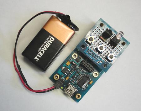
To demonstrate this capability, I constructed a battery-powered remote control transmitter, using a MoBoStamp-pe and a Parallax BS2pe Prototyping Daughterboard (a bargain at $1.95, BTW). The only additional components required were three push-button switches, a resistor, and an IR LED (which was in my junk box and probably came from Radio Shack). Here's a photo of the finished setup. There's also an IR receiver onboard, which isn't hooked up yet but is there in anticipation of future projects.

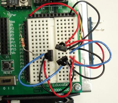
The objective of this project is to control a BOE Bot using the three buttons for forward, reverse, and turning motions. To make this happen, the BOE Bot needs an IR receiver — or three. I did use three IR receivers, aimed outward in a roughtly equilateral triangle. This is done so the BOE Bot can pick up the remote control signal from almost any angle. Here's a photo of the arrangement:

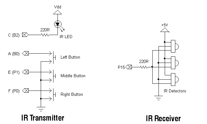
Because the receivers are wired internally as an open-collector transistor with a pullup (see datasheet), their outputs can be paralleled. In this way, any receiver that detects a carrier can pull the output down. The following schematics illustrate both the transmitter and receiver configurations:

In the original GPIO3 firmware provided with the MoBo, one can configure ports 2 and 3 as PWM outputs with a base frequency of 37.5KHz and any duty cycle from 0 to 100%. The new, version 5 (beta) firmware takes this a step further, allowing the PWM output (or any output) to be modulated by a serial data stream from the BASIC Stamp. By assigning a 50% duty cycle and driving an IR LED with the modulated output, it's possible to transmit data to a remote receiver. The documentation in the attached zip explains how to do this. The remote control app uses the following BS2pe source code to read the buttons and send the commands to the remote receiver:
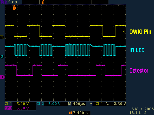
Whenever a button is pressed, the command for that button is sent via the IR LED to the receivers on the BOE Bot. Here is a scope snapshot that shows the data sent and the data received. The top trace shows the output of the BASIC Stamp SEROUT command as sent to the AVR's owio pin. The second trace shows the signal at the IR LED from the AVR coprocessor. It's a 37.5KHz carrier modulated by the serial data. The last trace shows the output of the triple IR receiver on the BOE Bot. One thing to notice here is the delay, both in pulling the output down, and the greater delay in returning it to a high state. The asymmetry in these delays will limit the maximum reliable baud rate. In fact, the 2400 baud used in this demo is probably about as high as you'd want to go.

For this demo I used a Parallax ServoPAL to control the motors on the BOE Bot. This permits a longer SERIN timeout period (200ms here) than the 20ms that would be afforded by having to refresh the servos with PBASIC code. Here's the BOE Bot program:
In operation, when the left button on the remote is pressed, the BOE Bot moves forward, continuing until the button is released. The middle button, similarly, causes reverse movement, and the right button causes the BOE Bot to turn. Turning is where the triple IR receiver comes in handy, since any single receiver will quickly rotate away from the transmitter's output and lose contact. With three receivers, one will always be within angular range of the transmitter.
I've had a lot of fun with this setup, and it suggests many more applications. I'm anxious to build up another proto board and try two-way communication with another MoBo!
-Phil
Post Edited (Phil Pilgrim (PhiPi)) : 3/7/2008 5:49:24 AM GMT
The Parallax BASIC Stamp 2pe Motherboard (a.k.a. MoBoStamp-pe) includes two AVR coprocessors. Each is capable of producing PWM output, unattended, at a frequency of 37.5KHz. This happy coincidence makes them nearly perfect (within 500Hz) for generating the required carrier for IR transmission. The only thing lacking was the proper firmware. That situatation has now been remedied. The attached zip includes the gpio5_beta upgrade to the stock gpio3 firmware, with which it is upward compatible. With the new firmware, it is now possible to modulate a 37.5KHz PWM carrier with serial data (via SEROUT) or any other code that the BASIC Stamp can generate.
To demonstrate this capability, I constructed a battery-powered remote control transmitter, using a MoBoStamp-pe and a Parallax BS2pe Prototyping Daughterboard (a bargain at $1.95, BTW). The only additional components required were three push-button switches, a resistor, and an IR LED (which was in my junk box and probably came from Radio Shack). Here's a photo of the finished setup. There's also an IR receiver onboard, which isn't hooked up yet but is there in anticipation of future projects.
The objective of this project is to control a BOE Bot using the three buttons for forward, reverse, and turning motions. To make this happen, the BOE Bot needs an IR receiver — or three. I did use three IR receivers, aimed outward in a roughtly equilateral triangle. This is done so the BOE Bot can pick up the remote control signal from almost any angle. Here's a photo of the arrangement:
Because the receivers are wired internally as an open-collector transistor with a pullup (see datasheet), their outputs can be paralleled. In this way, any receiver that detects a carrier can pull the output down. The following schematics illustrate both the transmitter and receiver configurations:
In the original GPIO3 firmware provided with the MoBo, one can configure ports 2 and 3 as PWM outputs with a base frequency of 37.5KHz and any duty cycle from 0 to 100%. The new, version 5 (beta) firmware takes this a step further, allowing the PWM output (or any output) to be modulated by a serial data stream from the BASIC Stamp. By assigning a 50% duty cycle and driving an IR LED with the modulated output, it's possible to transmit data to a remote receiver. The documentation in the attached zip explains how to do this. The remote control app uses the following BS2pe source code to read the buttons and send the commands to the remote receiver:
' {$STAMP BS2pe}
' {$PBASIC 2.5}

'--------[noparse][[/noparse] IR Remote Transmitter Program for MoBoStamp-pe ]----------
'
' Requires AVR firmware GPIO5.hex

owio    PIN 6                        'Use 10 for socket "A"; 6 for socket "B".
midsw   PIN 1                        'Use 9 for socket "A"; 1 for socket "B".
rtsw    PIN 0                        'Use 8 for socket "A"; 0 for socket "B".

baud    CON 396 + $8000              '2400 baud, open drain.

pbsw    VAR Bit
command VAR Byte

PAUSE 10                             'Wait for AVR to reset.
DO                                   'Do forever.
  command = 0                        'Clear command byte.
  OWOUT 6, 0, [noparse][[/noparse]$40]                  'Read lefthand switch from AVR w/pullup.
  OWIN 6, 4, [noparse][[/noparse]pbsw]
  IF (pbsw = 0) THEN                 'Lefthand switch pressed?
    command = "F"                    '  Yes: Command "Forward".
  ELSEIF (midsw = 0) THEN            '  No:  Middle switch pressed?
    command = "R"                    '         Yes: Command "Reverse".
  ELSEIF (rtsw = 0) THEN             '         No:  Right switch pressed?
    command = "T"                    '                Yes: Command "Turn".
  ENDIF
  IF (command) THEN                  'Any switch pressed?
    OWOUT owio, 1, [noparse][[/noparse]$66, $80]        '  Yes: Prep AVR for modulated PWM, 50% duty.
    SEROUT owio, baud, [noparse][[/noparse]"$", command, CR] '  Send command to IR LED
    HIGH owio                        '       Exit from modulation mode,
    PULSOUT owio, 1                  '         using a short pulse.
    INPUT owio                       '       Keep owio as an input.
  ENDIF
LOOP
Whenever a button is pressed, the command for that button is sent via the IR LED to the receivers on the BOE Bot. Here is a scope snapshot that shows the data sent and the data received. The top trace shows the output of the BASIC Stamp SEROUT command as sent to the AVR's owio pin. The second trace shows the signal at the IR LED from the AVR coprocessor. It's a 37.5KHz carrier modulated by the serial data. The last trace shows the output of the triple IR receiver on the BOE Bot. One thing to notice here is the delay, both in pulling the output down, and the greater delay in returning it to a high state. The asymmetry in these delays will limit the maximum reliable baud rate. In fact, the 2400 baud used in this demo is probably about as high as you'd want to go.
For this demo I used a Parallax ServoPAL to control the motors on the BOE Bot. This permits a longer SERIN timeout period (200ms here) than the 20ms that would be afforded by having to refresh the servos with PBASIC code. Here's the BOE Bot program:
' {$STAMP BS2}
' {$PBASIC 2.5}

'-------[noparse][[/noparse] IR Remote Receiver Program for BOE Bot ]------------------

ServoPAL  PIN 12
IR        PIN 15

command   VAR Byte

'-------[noparse][[/noparse] Initialize ServoPAL ]--------------------------------------

INPUT ServoPAL                'Make sure ServoPAL isn't being driven.
DO : LOOP UNTIL ServoPAL      'Wait for ServoPAL to power up.

LOW ServoPAL                  'Set pin to an output and hold it low
PAUSE 100                     '  for 100mS to reset ServoPAL.
HIGH ServoPAL                 'Raise the pin.
PAUSE 100

'-------[noparse][[/noparse] Main Program Loop ]----------------------------------------

DO                            'Do forever.
  SERIN IR, 396, 200, halt, [noparse][[/noparse]WAIT("$"), command] 'Get command from IR.
  IF (command = "F") THEN     'Command "Forward".
    PULSOUT ServoPAL, 500
    PULSOUT ServoPAL, 1000
  ELSEIF (command = "R") THEN 'Command "Reverse".
    PULSOUT ServoPAL, 1000
    PULSOUT ServoPAL, 500
  ELSEIF (command = "T") THEN 'Command "Turn".
    PULSOUT ServoPAL, 725
    PULSOUT ServoPAL, 725
  ENDIF
  GOTO LoopEnd                'Noise. Keep doin' what we're doin'.
Halt:
    PULSOUT ServoPAL, 2000    'SERIN timed out, so halt.
    PULSOUT ServoPAL, 2000
LoopEnd:
LOOP
In operation, when the left button on the remote is pressed, the BOE Bot moves forward, continuing until the button is released. The middle button, similarly, causes reverse movement, and the right button causes the BOE Bot to turn. Turning is where the triple IR receiver comes in handy, since any single receiver will quickly rotate away from the transmitter's output and lose contact. With three receivers, one will always be within angular range of the transmitter.
I've had a lot of fun with this setup, and it suggests many more applications. I'm anxious to build up another proto board and try two-way communication with another MoBo!
-Phil
Post Edited (Phil Pilgrim (PhiPi)) : 3/7/2008 5:49:24 AM GMT