Shop OBEX P1 Docs P2 Docs Learn Events
Inferred start/finish line detector with timer. For co2 cars!!! — Parallax Forums

Inferred start/finish line detector with timer. For co2 cars!!!

Tech-ManTech-Man Posts: 100
edited 2012-01-22 19:23 in BASIC Stamp
I have a project idea but I have no Idea how to start. Nor do I know if the BS1 can even do it.
·
Ok so we do these co2 car races at school in Power and Energy class, if you don’t know what a co2 car is ill tell you real quick. There little cars made from a block of wood. You have two eye hocks on the bottom that a fishing line runs through (runs down the hall about 100 feet). Then you put one of them small co2 canisters in the back and use this thing to launch them. ·They can get up to about 125mph believe it or not. There sort of like pinewood cars but way cooler.
DSCF4019.jpg


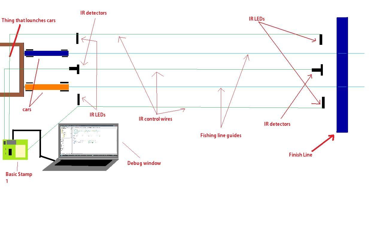
We time them with a stop watch but I was thinking there has to be a way to use inferred detectors to time them. Since it would be a whole lot faster and more accurate. ·Then the BS1 could debug the winner and maybe even its speed theoretically. Here is a drawing of what the sensors would look like.
·
I’m just wondering is here an easy (I’m not that experienced) way to program all this. Or any information on using ordinary IR LEDs. Thanks a ton I think the teacher would really like this and would probably invest in the parts for his own. He’s cool like that!!!


ir.jpg

▔▔▔▔▔▔▔▔▔▔▔▔▔▔▔▔▔▔▔▔▔▔▔▔
There are no Undo buttons in life.

Comments

  • ercoerco Posts: 20,244
    edited 2008-03-26 02:38
    TM:·Great project, and infrared timing·is a perfect application for a BS1! You'll have fun and learn a ton in the process. Order a Basic Stamp 1 Project Board (order several, it's the best deal in town at $15) and a programming cable if you need one. You'll have to build your start & finish gates to shield your IR detectors. Go to Radio Shack and get two phototransistors and two IR LEDs. They sell them in pairs, but all of my experience has been with the seperately packaged ones, they're more consistent. You'll have to optically align your LEDs and phototransistors and bury them in deep holes to shield them from outside light. You'll use fixed resistors to calibrate it for a fairly consistent ambient light level. Don't expect it to work outdoors, sunlight will saturate your phototransistor detectors. I would suggest that you use wood (2x4s or such) to make twin·arches at the start and finish line. Sketch attached. You'll have to decide on a maximum height & width for your cars to do this.· Drill your holes straight and ensure alignment by either sighting through the holes or using a dowel rod during assembly. Paint inside the arches and inside the LED/phototransistor holes ultra flat black (Krylon spray paint) to minimize reflection.·You'll have 4 wires running from your Stamp to the start line and 4 more to the finish line (+5 volts, ground, and 2 sensor connections each). Polarity matters on the LEDs and the phototransistors. Mainly, you need to worry about shielding your phototransistors from each other and from outside light. You'll need minimal extra components (probably just carefully chosen resistors, based on your particular layout and ambient lighting) to make it work properly with your stamp. Using a laptop or computer is just fine, and if you like, later you can add an LCD display for a standalone unit. This is how I'd do it, but·I'll bet·you'll get lots of help from this forum, there are plenty of smart people here. If you like·my direction and need help with the circuitry and/or programming, just ask. Happy to help, I've done this same project for Hot Wheels and Pinewood Derby races.

    ▔▔▔▔▔▔▔▔▔▔▔▔▔▔▔▔▔▔▔▔▔▔▔▔
    ·"If you build it, they will come."
    400 x 280 - 12K
  • Tech-ManTech-Man Posts: 100
    edited 2008-03-26 03:29
    Well thanks I’m glad you’re so willing to help a beginner like me. It also helps that you have done this before. ·So I had envisioned exactly what you drew up for holding the sensors. I was thinking the best way to do it would be to have the sensors as low to the ground as possible like .25” so that you’re bound to hit some part of the car most likely he wheels. ·Those Inferred LEDs and photo transistors are sort of expensive when you figure you need 4 of each kind. I may have some lying around ill have to check. Would those little things from inside printers and stuff work.· There like an emitter and detector attached with a space in between. I mean id have to split them apart but that’s no big deal. And i have a tone of them.·I don’t know maybe they wouldn’t be strong enough. ·But yeah I have a homework board already and a ton of wire and other stuff so maybe I can do this; all I need is the emitters and detectors. Do you have any code from another project that I could take a look at. I’m good with the physical side of most this it’s just the programming that I get hung up on. And yeah I just had an idea at the beginning could you have just one emitter and one detector have it go across the whole track. Idk if that would work but it seems like it would make less code. ·I really like the idea of someday getting a display. That would be slick.· Well anyway hope to hear back from you.

    ▔▔▔▔▔▔▔▔▔▔▔▔▔▔▔▔▔▔▔▔▔▔▔▔
    There are no Undo buttons in life.
  • ercoerco Posts: 20,244
    edited 2008-03-26 04:27
    Very good, sounds like you're plenty capable. Those parts are cheap at Radio Shack, BTW. The LEDs (276-143) are $1.99 each and the PTX (phototransistors, 276-145) are a bargain at $1.59. If you have a good electronics store around you that carries Jim-Paks, you can get 6 LEDs for about $3 (TLN110-6) and 6 PTX for about $3 (IRD500JP-6). To be honest, I have made sensors that worked fine with Hot Wheels cars by using only a phototransistor under the track pointing up. It just used ambient room light and looked for a shadow to pass above it. But that was finicky to calibrate, and the Hot Wheels cars are all similar shape and the cars' chasses were all very low and similar. Looks like your cars come in all shapes and sizes, so I agree that breaking a low horizontal beam with your cars' front wheels is the way to go. I recommend that you just buy the parts instead of scrounging, so that everything you have is consistent and replaceable if need be. It's easy to mangle an LED or PTX when you're wiring it up·and glueing it into a deep hole.

    Please confirm whether you have a Stamp 1 Project Board or a Stamp 2 Homework board. They're similar, but the timing calibrations will be different. I can help you with the code, and you can use it and modify it as you like. It will be a few timing loops running as fast as possible (your cars are quick, probably 1-2 seconds start to finish?) that you can calibrate pretty well to seconds, and if you standardize the start-finish distance, you could calculate an actual and scale speed.
    You'll have 8 or 16 pins, depending on Stamp 1 or 2. It's easy enough to time both lanes individually with 4 pins as inputs. You can use the extra pins as outputs and make a red/green LED drag race start Christmas tree, and/or an LED "Winning Lane"/finish flag indicator, or generate some sound for the Christmas tree or finish line through a speaker. Very flexible system. I'll mock up a circuit and get you·some code in a day or two. Let me know which Stamp you have, ASAP.

    ▔▔▔▔▔▔▔▔▔▔▔▔▔▔▔▔▔▔▔▔▔▔▔▔
    ·"If you build it, they will come."
  • Tech-ManTech-Man Posts: 100
    edited 2008-03-26 11:31
    Thanks a ton,· yeah i have a BS1 with 8 pins. I wish there was an electronics part store in my area· but i have yet to find any except Radio Shack. well i may just go get them parts.

    ▔▔▔▔▔▔▔▔▔▔▔▔▔▔▔▔▔▔▔▔▔▔▔▔
    There are no Undo buttons in life.
  • ercoerco Posts: 20,244
    edited 2008-03-26 14:16
    What's a typical time for a car to go 100 feet, and what's a reasonable maximum time (stop timing if the car hasn't crossed the finish line). You say your cars race 100 feet, that's a long way to run 4 seperate wires. Start looking for a shielded cable with at least 3 conductors in it, we'll ground the shield and hopefully prevent outside signal interference. Do you plan to keep your Stamp and laptop right by the starting line?

    ▔▔▔▔▔▔▔▔▔▔▔▔▔▔▔▔▔▔▔▔▔▔▔▔
    ·"If you build it, they will come."
  • Tech-ManTech-Man Posts: 100
    edited 2008-03-26 15:25
    Well the lane is 100' long but we time them at about 50' for the msximum speed. Curently i have the fastest car at about .94 sec but·they could go faster and a maximum time would be around 1.5 sec but they may go slower you·never know. I have a·ton of·6 conductor data cable,·come cat-5·and·some other stuff.·Nune of wich are shelded. When i·get out of robotics om hopeing to go to Radio Shack ad pick up some parts. Either·way is fine but·im almost thinking the finish line would be better. So yeah any code you may have would be nice to take a look at. Iv never worked·with IR on a BS yet so thanks for helping.

    ▔▔▔▔▔▔▔▔▔▔▔▔▔▔▔▔▔▔▔▔▔▔▔▔
    There are no Undo buttons in life.
  • ercoerco Posts: 20,244
    edited 2008-03-26 15:35
    Those are some Hot Wheels! You have options. You can set your timing arches at the start and finish for an overall time, or set them 5 feet apart at the 50-foot mark to measure peak speed. Same program and circuit, but you'll use different numbers to calibrate.

    ▔▔▔▔▔▔▔▔▔▔▔▔▔▔▔▔▔▔▔▔▔▔▔▔
    ·"If you build it, they will come."
  • ercoerco Posts: 20,244
    edited 2008-03-26 22:03
    Tech-Man:

    Here's a schematic diagram of one of the four sensors you'll need to make using the Radio Shack parts I mentioned.·The mechanical construction is more demanding than the electrical here. Make sure your LEDs and phototransistors (PTX) are properly aligned with each other, and shield your PTXs from each other and from·outside light. Recess·them a half-inch inside 1/4" diameter holes, and spray paint the inside of those holes ultra flat black to reduce reflections. Hot melt glue works OK to hold them in, but keep the front lens of the LEDs & PTXs perfect. The 220 ohm resistors worked fine for me, but you might have to adjust up or down for your particular geometry and construction. Lower resistance (down to 150 ohms) lets more current flow, giving you a stronger LED signal to·"turn on" the PTX. (But use the highest resistor that·works to save battery life.) Your cars will block this IR signal and the PTX will "turn off". I use these terms loosely, because the PTX is a voltage divider that outputs a fluctuating analog signal. The Stamp does an A/D conversion, anything lower than 1.2 volts is low, or off, and above 1.2 is high or on. Watch polarity on your LEDs and PTXs; there's always a flat spot by the negative lead, which goes toward ground. You'll do the right thing.

    BTW, the drawing shows 3 wires going from the sensor to the Stamp, but two of those are common: +5 volts and ground. That's why you'll only need 4 long wires running to the far end of your track, +5V, ground, and 2 going to·your individual PTX junctions.

    I'll get some code to you in a day or so. If you get the parts and want to play around with the sensors, you can plug them into your Project Board breadboard area (use pin 7) and make & break the IR beam. This bit of·code·here·monitors pin 7 status.··0= IR beam broken,··· 1= IR beam sensed. Cheers.

    ' {$STAMP BS1}
    ' {$PBASIC 1.0}
    aaa[noparse]:D[/noparse]EBUG PIN7:GOTO aaa

    ▔▔▔▔▔▔▔▔▔▔▔▔▔▔▔▔▔▔▔▔▔▔▔▔
    ·"If you build it, they will come."
    660 x 350 - 47K
  • Tech-ManTech-Man Posts: 100
    edited 2008-03-27 03:11
    I have never seen a MegOhm resister, or have I and just did not know it? One question so far, what purpose does that resister serve anyways, seems real large. And why does it go to ground? I did not get to the store yet but I’m hopeing to soon. Maybe I can get there this weekend then I’ll have all next week to work on it. I have spring break.

    ▔▔▔▔▔▔▔▔▔▔▔▔▔▔▔▔▔▔▔▔▔▔▔▔
    There are no Undo buttons in life.
  • ercoerco Posts: 20,244
    edited 2008-03-27 16:00
    TM: 1 megohm is a million ohms. That is a high value, but readily available and a typical value for a series resistor used in this type of voltage-divider application to get high sensitivity. The resistor goes to ground and the PTX goes to B+ so that their junction gives a voltage proportional to the intensity of the IR signal received. Sort of like how a potentiometer voltage divider works. All we care about is that the signal is readable by the Stamp, so the circuit arrangement (PTX on top and resistor on the bottom, instead of the opposite) and resistor value are chosen such that the voltage extremes are well above and below the Stamp's high/low threshold of 1.2 volts .

    I told you that you'd learn new things... In a while, this stuff will be second nature to you and you'll be answering other people's questions in this forum!

    ▔▔▔▔▔▔▔▔▔▔▔▔▔▔▔▔▔▔▔▔▔▔▔▔
    ·"If you build it, they will come."
  • ercoerco Posts: 20,244
    edited 2008-03-27 16:11
    I should have mentioned previously to mount the two resistors (220 ohm and 1 megohm) per sensor on the start and finish gates to minimize wiring. So you'll have 4 wires going to each gate (+5 common, ground common, and two sensor wires). Since each gate has two lanes, there are two sensors per gate. Thus, a total of two LEDs, two PTXs, two 220 ohm and two 1-megohm resistors per gate.

    ▔▔▔▔▔▔▔▔▔▔▔▔▔▔▔▔▔▔▔▔▔▔▔▔
    ·"If you build it, they will come."
  • Tech-ManTech-Man Posts: 100
    edited 2008-03-28 02:31
    Yeah I know what a mega ohm is its just I didn’t know they went that high. But now that I think about it, most likely they go even higher. We finished up the car racing today my car ended up coming in 2ed. But I’m still going to build this circuit and ask my teacher if we can just set up the track someday to try it out. Ok so I checked and I’m still not sure but I think I may have told you wrong about the track length it may be even longer. ·Well whatever ill find out sometime what the real length is, but I bet that’s just a miner thing to switch in the code, or is it? Like I said if I can get some money I’ll go get those parts next week over spring break and work on some arches. If you don’t mind me asking, what field of work are you in? Does it have to do with electronics or it this just a hobby.·

    ▔▔▔▔▔▔▔▔▔▔▔▔▔▔▔▔▔▔▔▔▔▔▔▔
    There are no Undo buttons in life.
  • ercoerco Posts: 20,244
    edited 2008-03-28 16:01
    Very good. Build it and git 'er done! Exact length of your track only matters if you want the software to display a scale or real speed. Otherwise, you just have it act as a timer and you can put the sensors anywhere you want. You can easily calculate speed yourself once you have an accurate time. BTW, on your launch mechanism, is there anything to guarantee that both cars start at exactly the same time? If not, the last car to leave could still have the lowest ET. I'm asking because you might consider adding a Christmas tree countdown, and each car is launched individually by its driver. Just like real drag racing, you could calculate your reaction time plus ET, and you could "red-light" if you jumped the gun and launched before the Christmas tree went green. All that's required would be adding a few LEDs to your Stamp board, all the timing gates remain the same.

    To answer your question, I'm a toy designer. I make race tracks for Hot Wheels cars, so that's why I said I've done a fair amount of this race timing thing. I have a BSME degree, but I've done all the geeky electronic things my whole life as a hobby. Ham radio, electronics, video, robotics, etc. Shameless plug: check out my soon-to-be released SKY JUMP set for the new Speed Racer movie. Pretty cool.

    So my recommendation to you: Stay in school and buy Hot Wheels!

    ▔▔▔▔▔▔▔▔▔▔▔▔▔▔▔▔▔▔▔▔▔▔▔▔
    ·"If you build it, they will come."
  • Tech-ManTech-Man Posts: 100
    edited 2008-03-30 21:48
    So I’m talking to the guy that may have designed some of the toys I played with as a kid, that’s pretty cool. That SKY JUMP thing sure has some crazy curves.

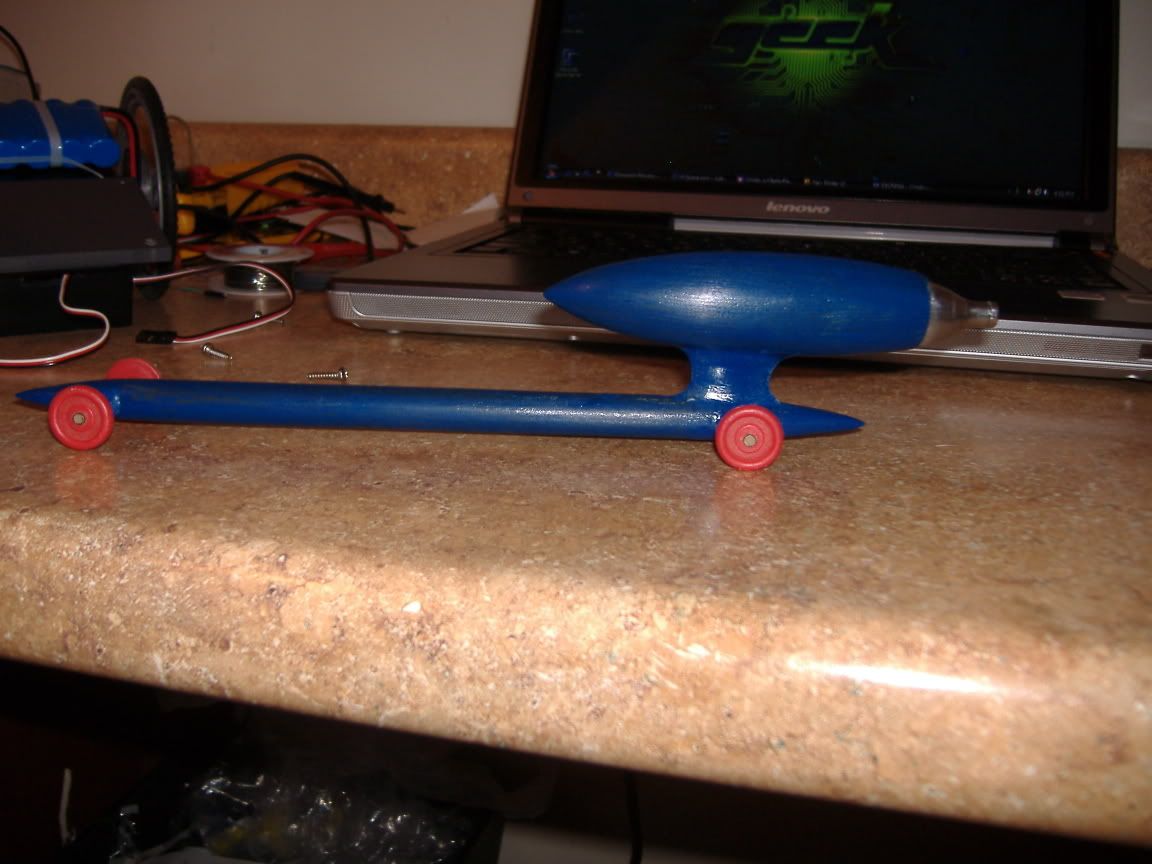
    But yeah the cars get launched at the exact same time. Here is a diagram of the launching mechanism. Pretty simple a weight like a pendulum comes down and strikes a pin that punctures a hole in the co2 cartridge.·
    ·
    ·
    I still haven’t picked up any IR stuff, but while were waiting check out our robot we took to this year’s FRC regionals. We got 8th place out of 40 teams. Were team 2197 Las Pumas
    http://flickr.com/photos/justinhulbert/2278485200/
    http://flickr.com/photos/justinhulbert/2337993339/sizes/l/
    http://flickr.com/photos/justinhulbert/2338017275/sizes/l/
    http://flickr.com/photos/justinhulbert/2338086289/sizes/l/

    ▔▔▔▔▔▔▔▔▔▔▔▔▔▔▔▔▔▔▔▔▔▔▔▔
    There are no Undo buttons in life.
    1218 x 377 - 32K
    c02.jpg 31.9K
  • ercoerco Posts: 20,244
    edited 2008-03-31 20:12
    Congrats, that robot is complex and quite an accomplishment! Let me know when you build your IR gates and I'll get you the code for your BS1.

    ▔▔▔▔▔▔▔▔▔▔▔▔▔▔▔▔▔▔▔▔▔▔▔▔
    ·"If you build it, they will come."
  • Tech-ManTech-Man Posts: 100
    edited 2008-03-31 21:39
    Yeah you could say it’s pretty complex, the operating code for it is done in EasyC. Took me about 10 minutes to write the whole program, it’s all flow charts which makes it supper easy. ·But yeah ill get with you right away when I get the parts.

    ▔▔▔▔▔▔▔▔▔▔▔▔▔▔▔▔▔▔▔▔▔▔▔▔
    There are no Undo buttons in life.
  • ercoerco Posts: 20,244
    edited 2008-05-31 20:44
    Tech-Man: I see you're making ROVs now. What ever became of this timer project?

    ▔▔▔▔▔▔▔▔▔▔▔▔▔▔▔▔▔▔▔▔▔▔▔▔
    ·"If you build it, they will come."
  • Tech-ManTech-Man Posts: 100
    edited 2008-05-31 21:18
    I never did make it· due to time and money at the time, but like i said i got 3 boe bots so now i have the detectors i may still try it sometime.· Thanks

    ▔▔▔▔▔▔▔▔▔▔▔▔▔▔▔▔▔▔▔▔▔▔▔▔
    There are no Undo buttons in life.
  • KievlaninKievlanin Posts: 55
    edited 2012-01-22 16:36
    See Pal Romsky BS1 project: http://forums.parallax.com/showthread.php?137222-PBASIC-help
    I have tested his design. It works. Pictures included. I used buttons in place of light gates.

    I think this will fit your project.

    By the way! Great "cars" I never sought people will do this. But this is the rockets!
  • Dave HeinDave Hein Posts: 6,347
    edited 2012-01-22 19:23
    Tech-Man, it looks like that should be a fun project. I build a Pinewood Derby finish line timer a few years ago. It monitored the finish line of a track that could race 3 cars at a time, and it would indicate which cars came in first, second and third using LEDs. I used a logic state machine based on an EPROM instead of using a processor. The timer came in handy several times when there appeared to be a tie between two cars. It had a resolution time of 1 milli-second, and it did a good job of determing which car came in first.

    One thing we found that was very important was to limit the field of vision of the optical sensor. We did this by having it look through a quarter-inch hole that was about 3 inches long. This limited the amount of ambient light that it see. Otherwise, you may have problems if the ambient light is very bright.
  • i know this thread is pretty old, but im building a co2 race car track in my mechanical engineering class and we were thinking of utilizing a similar setup on ours. how did this build turn out? im pretty new to the breadboard and programming aspects, but can this be adapted for arduino use? thats the controller i have. thanks in advance for any and all help!
  • kwinnkwinn Posts: 8,697
    It could work fine with an arduino.
  • ercoerco Posts: 20,244
    It would burst into flame if connected to an Arduino.
  • erco wrote: »
    It would burst into flame if connected to an Arduino.

    :lol:
Sign In or Register to comment.