Inferred start/finish line detector with timer. For co2 cars!!!
I have a project idea but I have no Idea how to start. Nor do I know if the BS1 can even do it.
·
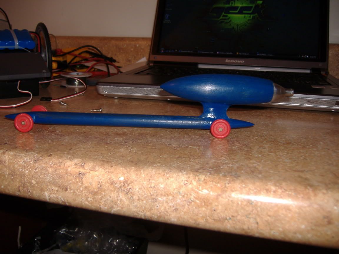
Ok so we do these co2 car races at school in Power and Energy class, if you don’t know what a co2 car is ill tell you real quick. There little cars made from a block of wood. You have two eye hocks on the bottom that a fishing line runs through (runs down the hall about 100 feet). Then you put one of them small co2 canisters in the back and use this thing to launch them. ·They can get up to about 125mph believe it or not. There sort of like pinewood cars but way cooler.

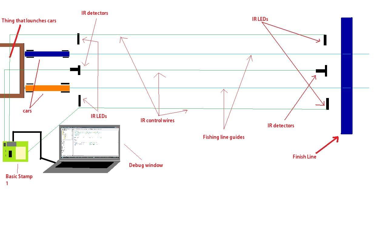
We time them with a stop watch but I was thinking there has to be a way to use inferred detectors to time them. Since it would be a whole lot faster and more accurate. ·Then the BS1 could debug the winner and maybe even its speed theoretically. Here is a drawing of what the sensors would look like.
·
I’m just wondering is here an easy (I’m not that experienced) way to program all this. Or any information on using ordinary IR LEDs. Thanks a ton I think the teacher would really like this and would probably invest in the parts for his own. He’s cool like that!!!

▔▔▔▔▔▔▔▔▔▔▔▔▔▔▔▔▔▔▔▔▔▔▔▔
There are no Undo buttons in life.
·
Ok so we do these co2 car races at school in Power and Energy class, if you don’t know what a co2 car is ill tell you real quick. There little cars made from a block of wood. You have two eye hocks on the bottom that a fishing line runs through (runs down the hall about 100 feet). Then you put one of them small co2 canisters in the back and use this thing to launch them. ·They can get up to about 125mph believe it or not. There sort of like pinewood cars but way cooler.

We time them with a stop watch but I was thinking there has to be a way to use inferred detectors to time them. Since it would be a whole lot faster and more accurate. ·Then the BS1 could debug the winner and maybe even its speed theoretically. Here is a drawing of what the sensors would look like.
·
I’m just wondering is here an easy (I’m not that experienced) way to program all this. Or any information on using ordinary IR LEDs. Thanks a ton I think the teacher would really like this and would probably invest in the parts for his own. He’s cool like that!!!

▔▔▔▔▔▔▔▔▔▔▔▔▔▔▔▔▔▔▔▔▔▔▔▔
There are no Undo buttons in life.


Comments
▔▔▔▔▔▔▔▔▔▔▔▔▔▔▔▔▔▔▔▔▔▔▔▔
·"If you build it, they will come."
▔▔▔▔▔▔▔▔▔▔▔▔▔▔▔▔▔▔▔▔▔▔▔▔
There are no Undo buttons in life.
Please confirm whether you have a Stamp 1 Project Board or a Stamp 2 Homework board. They're similar, but the timing calibrations will be different. I can help you with the code, and you can use it and modify it as you like. It will be a few timing loops running as fast as possible (your cars are quick, probably 1-2 seconds start to finish?) that you can calibrate pretty well to seconds, and if you standardize the start-finish distance, you could calculate an actual and scale speed.
You'll have 8 or 16 pins, depending on Stamp 1 or 2. It's easy enough to time both lanes individually with 4 pins as inputs. You can use the extra pins as outputs and make a red/green LED drag race start Christmas tree, and/or an LED "Winning Lane"/finish flag indicator, or generate some sound for the Christmas tree or finish line through a speaker. Very flexible system. I'll mock up a circuit and get you·some code in a day or two. Let me know which Stamp you have, ASAP.
▔▔▔▔▔▔▔▔▔▔▔▔▔▔▔▔▔▔▔▔▔▔▔▔
·"If you build it, they will come."
▔▔▔▔▔▔▔▔▔▔▔▔▔▔▔▔▔▔▔▔▔▔▔▔
There are no Undo buttons in life.
▔▔▔▔▔▔▔▔▔▔▔▔▔▔▔▔▔▔▔▔▔▔▔▔
·"If you build it, they will come."
▔▔▔▔▔▔▔▔▔▔▔▔▔▔▔▔▔▔▔▔▔▔▔▔
There are no Undo buttons in life.
▔▔▔▔▔▔▔▔▔▔▔▔▔▔▔▔▔▔▔▔▔▔▔▔
·"If you build it, they will come."
Here's a schematic diagram of one of the four sensors you'll need to make using the Radio Shack parts I mentioned.·The mechanical construction is more demanding than the electrical here. Make sure your LEDs and phototransistors (PTX) are properly aligned with each other, and shield your PTXs from each other and from·outside light. Recess·them a half-inch inside 1/4" diameter holes, and spray paint the inside of those holes ultra flat black to reduce reflections. Hot melt glue works OK to hold them in, but keep the front lens of the LEDs & PTXs perfect. The 220 ohm resistors worked fine for me, but you might have to adjust up or down for your particular geometry and construction. Lower resistance (down to 150 ohms) lets more current flow, giving you a stronger LED signal to·"turn on" the PTX. (But use the highest resistor that·works to save battery life.) Your cars will block this IR signal and the PTX will "turn off". I use these terms loosely, because the PTX is a voltage divider that outputs a fluctuating analog signal. The Stamp does an A/D conversion, anything lower than 1.2 volts is low, or off, and above 1.2 is high or on. Watch polarity on your LEDs and PTXs; there's always a flat spot by the negative lead, which goes toward ground. You'll do the right thing.
BTW, the drawing shows 3 wires going from the sensor to the Stamp, but two of those are common: +5 volts and ground. That's why you'll only need 4 long wires running to the far end of your track, +5V, ground, and 2 going to·your individual PTX junctions.
I'll get some code to you in a day or so. If you get the parts and want to play around with the sensors, you can plug them into your Project Board breadboard area (use pin 7) and make & break the IR beam. This bit of·code·here·monitors pin 7 status.··0= IR beam broken,··· 1= IR beam sensed. Cheers.
' {$STAMP BS1}
' {$PBASIC 1.0}
aaa[noparse]:D[/noparse]EBUG PIN7:GOTO aaa
▔▔▔▔▔▔▔▔▔▔▔▔▔▔▔▔▔▔▔▔▔▔▔▔
·"If you build it, they will come."
▔▔▔▔▔▔▔▔▔▔▔▔▔▔▔▔▔▔▔▔▔▔▔▔
There are no Undo buttons in life.
I told you that you'd learn new things... In a while, this stuff will be second nature to you and you'll be answering other people's questions in this forum!
▔▔▔▔▔▔▔▔▔▔▔▔▔▔▔▔▔▔▔▔▔▔▔▔
·"If you build it, they will come."
▔▔▔▔▔▔▔▔▔▔▔▔▔▔▔▔▔▔▔▔▔▔▔▔
·"If you build it, they will come."
▔▔▔▔▔▔▔▔▔▔▔▔▔▔▔▔▔▔▔▔▔▔▔▔
There are no Undo buttons in life.
To answer your question, I'm a toy designer. I make race tracks for Hot Wheels cars, so that's why I said I've done a fair amount of this race timing thing. I have a BSME degree, but I've done all the geeky electronic things my whole life as a hobby. Ham radio, electronics, video, robotics, etc. Shameless plug: check out my soon-to-be released SKY JUMP set for the new Speed Racer movie. Pretty cool.
So my recommendation to you: Stay in school and buy Hot Wheels!
▔▔▔▔▔▔▔▔▔▔▔▔▔▔▔▔▔▔▔▔▔▔▔▔
·"If you build it, they will come."
But yeah the cars get launched at the exact same time. Here is a diagram of the launching mechanism. Pretty simple a weight like a pendulum comes down and strikes a pin that punctures a hole in the co2 cartridge.·
·
·
I still haven’t picked up any IR stuff, but while were waiting check out our robot we took to this year’s FRC regionals. We got 8th place out of 40 teams. Were team 2197 Las Pumas
http://flickr.com/photos/justinhulbert/2278485200/
http://flickr.com/photos/justinhulbert/2337993339/sizes/l/
http://flickr.com/photos/justinhulbert/2338017275/sizes/l/
http://flickr.com/photos/justinhulbert/2338086289/sizes/l/
▔▔▔▔▔▔▔▔▔▔▔▔▔▔▔▔▔▔▔▔▔▔▔▔
There are no Undo buttons in life.
▔▔▔▔▔▔▔▔▔▔▔▔▔▔▔▔▔▔▔▔▔▔▔▔
·"If you build it, they will come."
▔▔▔▔▔▔▔▔▔▔▔▔▔▔▔▔▔▔▔▔▔▔▔▔
There are no Undo buttons in life.
▔▔▔▔▔▔▔▔▔▔▔▔▔▔▔▔▔▔▔▔▔▔▔▔
·"If you build it, they will come."
▔▔▔▔▔▔▔▔▔▔▔▔▔▔▔▔▔▔▔▔▔▔▔▔
There are no Undo buttons in life.
I have tested his design. It works. Pictures included. I used buttons in place of light gates.
I think this will fit your project.
By the way! Great "cars" I never sought people will do this. But this is the rockets!
One thing we found that was very important was to limit the field of vision of the optical sensor. We did this by having it look through a quarter-inch hole that was about 3 inches long. This limited the amount of ambient light that it see. Otherwise, you may have problems if the ambient light is very bright.