

New Propeller Platform USB design
 Martin Hodge
Posts: 1,246
Martin Hodge
Posts: 1,246
Continuing from this thread...
It's alive and well!
It's 3am, more info after sleep.
--Update--
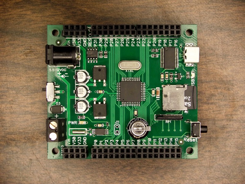
Here is a view of the SD card configured for P16-P19 operation.
The changes to the original design:
Most up-to-date layout attached, along with a pallpark cost breakdown in ods format. ppusb_rtc.zip
It's alive and well!
It's 3am, more info after sleep.
--Update--
Here is a view of the SD card configured for P16-P19 operation.
The changes to the original design:
- Added USB activity LED
- Surface mount power switch
- Reverse polarity protection diode
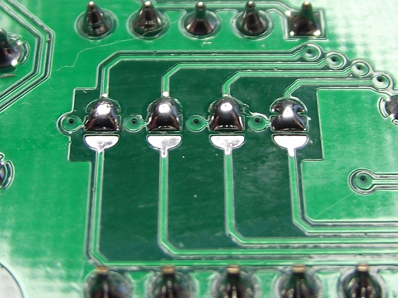
- Removable pull-up resistor pack for uSD card
- uSD card can be connected to P0-P3 or P16-P19 using solder bridge pads on the back
- Seiko RTC chip with rechargeable supercap battery backup
- External reset connection inserted in top header between P31 and GND
- J11 for access to RTC chip interrupt outputs
- Right angle reset button for easier access
Most up-to-date layout attached, along with a pallpark cost breakdown in ods format. ppusb_rtc.zip
Comments
Looks good, get some sleep!!
Hi Martin, it looks great!
I realise I am a little late with this and maybe you've though about it already.
Is there any way you can move the uSD card slot closer to the edge of the PCB?
The reason I ask is that more and more now I provide a case for my projects and uSD slots are always a pain to get right, this being so far from the board edge gives you very little chance of providing a usable slot.
regards,
Coley
Coley, I have noticed that and yes there is still time to make changes. I'm pretty sure there's going to be one more revision. Stay tuned.
-- Gordon
And when will they be available???
I thought the SPI suggestion worthwhile.
I don't need it (yet) but that's one of the real limitations of the Propeller - mo mem!
Price is important, of course, but WHENCANIHAVEONE???
Richard
Is it to early for me to pre-order one or two?
It's way too early to be talking about price, but I can definitely say it won't be less than GG was charging.
Until you started this, Martin, I was considering jumping back into the Propeller Platform game. My big gripe with the PP-USB is putting the uSD connections on P0..P3 (you've fixed that). FWIW, this is what I'd like to see:
P0..P15 are completely free of any onboard hardware
P16..P19 are used for the uSD
P27 is SPI MISO
P26 is SPI MOSI
P25 is SPI CLK
P24 would be the CS for an onboard SPI device
P23..P20 would be free
Jon, it's your design originally, yes? I wouldn't get my feelings hurt if you took it over to "go big" with it. (Which reminds me, I need to be sure everyone who's contributed gets adequate attribution.)
I would like independent access to the SPI buss and the SD card.
Yep; created the original version (DIP devices on the ExpressPCB miniboard layout) for my Nuts & Volts column. Nick had just started his business and I asked him to create kits for my column projects so that I wouldn't have to.
I often expand simple pin IO using I2C or SPI expansion chips. They're easy and plentiful.
The GG PPUSB is difficult to solder by hand especially near the SD card.
Will this board later be available for sale at Gadget Gangster website?
Great work !
Could you tell me where to find this kind of SD Slot and where you get the Eagle Lib for that part ?
Kind Regards
robby
Where will these be available and when? Will these be completed boards or kits?
I don't think this is an extreme example at all, J.
In fact, quite a reasonable approach.
(I like knobs better than up/down buttons).
Playing audio is pretty demanding work.
Even a dozen MS gap will be obvious. More would be down right unacceptable.
I also thought your I/O mapping was right on - and it leaves a few extra pins available there (high numbers)
to deal with a few extra toys.
Sixteen general purpose I/O pins, with all the necessary stuff already installed on this board -
looks like a real winner.