

Smart Pin Pulse Mode - Lags
 Christof Eb.
Posts: 1,584
Christof Eb.
Posts: 1,584
Hi,
I am using Smart Pin pulse mode to output a group of 16 microsteps for a step driver.
After starting the pulses, ct1 is set to the new start time of the next group.
After some calculations the cog does waitct1.
Then wxPin, wrPin, and wyPin is set newly, as the speed may have changed.
Typical pulse HIGH length and also LOW length is 15us.
The time lag between after waitct1 and after wyPin is 3.5us.
After several pulse groups however the LOW time is increased to about 45us. It looks as if one full cycle is lost.
As far as I understand I cannot preload the smart pin registers before the group is completely finished?
Perhaps someone has an idea? I have spent some hours on this.
Thanks a lot, Christof
Comments
Yes, a buffered command for pulse modes would solve it. No, none of the pulse modes have such buffering. I imagine Chip would gladly add command buffering in hindsight.
Yes, a fresh pulse count, written to Y, is only actioned at beginning of next "base period" cycle. Metronomic base period cycles begin cycling at rising DIR control.
PS: Base period value, in X[15:0], is reread upon each period cycle.
I've re-edited a few times now for clarity.
So I tried to find out more.
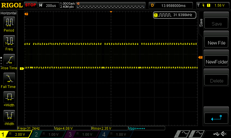
In this test I have set the ct1 time to 17cycles for each pulse group of 16 cycles. So there should always be a time lag of one cycle before the next group: As you can see, it is not!
This is very strange, as the smart pin mode is reset and newly set each time:
PRIMI(startPulses) { // ( x y pin -- ) starts smart mode pulses
        int pin= TOS; _drop();
        int y = TOS; _drop();
        int x= TOS; _drop();
        _pinclear(pin);
        _pinstart(pin,P_OE | P_PULSE, x, y);
}
compiles to (pr0 is Top Of Stack, pr4 is stack pointer):
For me this looks like a silicone bug, as neither dirl nor wrpin #0 does realign the timing????
Is such behaviour known?
I am aware, that a short time lag after a pulse group can not be avoided, as we have no double buffering. But here we have sometimes a lag that is much longer.
Is there a workaround?
Cheers Christof
There is an OBEX ebject for step/dir signal generation. There, I use NCO instead of pulse mode. I don't know why a fixed pulse-high time is used in so many pulse generators. IMHO it's much better to use 50/50 duty cycle. This way you can get rid of all the problems.
Ha! Finally found a workaround.")
The Transition Mode also does not reset it's base period counter, whatever you do. But it signals the IN signal directly after the last transition. So you can wait until IN is low and then setup newly during the time the output is low for the next group.
Hi Nicolas, thank you very much. I have studied your driver. As far as I understand there is a loop running at 800 cycles.
My method does at the moment only handle one axis at a time. On the plus side the Transitions Mode buys time to do the whole movement including ramp up and down within the same cog. Even in Forth. Seems to work up to 100kHz microstep frequency.
Cheers Christof
Yes, the NCO mode like the pulse mode also isn't buffered like the serial RX/TX modes. This means you have to write the registers at the exact right time and therefore a dedicated cog is required waiting with waitct to synchronize everything. But the P2 has plenty of power and you could handle multiple axes and also many other tasks in the same loop.